
G1 IOM Maitland by Stuart Rothwell

Feb 2024 - I have started researching the IOM locomotive Maitland. Below are my drawings so far. The first is of the cylinders showing the valve face which will pass through the frames as the original but the valves will be in a different orientation ie. horizontal not vertical, there is just not enough room to achieve assembly. The second is the axle boxes. I am a bit disappointed because I would have liked to have imitated the original suspension, but at 15mm scale it is just too small. So I have decided to use conventional suspension and fit scale dummy springs.
March 2024 - More drawings. Drawing IOM 3 is of sectional views through the steam chests located between the frames with the valve face horizontal and the steam chest cover in one piece across both allowing for a single exhaust port. Not seen it done like this before so hope it will work. IOM 4 is the steam chests themselves and is self explanatory. IOM 5 is the steam chest cover with the blast pipe connecter and transfer port between the two cylinders. IOM 6 & 7 are scale drawings of the wheels required, I have shown key dimensions only because the finished items will depend on the castings that I can find. I have found some drivers at the 2½ gauge society and some bogey wheel castings at Walsall Models, neither are exact scale but are probably good enough for me, if not the rivet counters. The next phase is to finalise the frame drawings which are done to scale but will need modifying to suite practicalities at this scale. The plan is to have a rolling chassis by the end of the summer and then carry on with the drawings, which will be the coupling rods and valve gear.
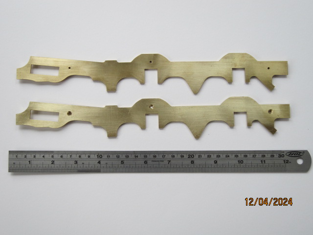
April 2024 - I have actually started the build of my IOM loco. Below is a photo of the completed frames. My next task is to make a mock-up in wood of one cylinder to check clearances, practicalities of manufacture and work out the best method of attachment.
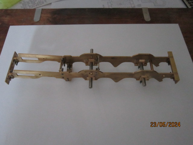
May 2024 - Below is a photo of the chassis so far, assembled complete with axle boxes. Now for the wheels, oh how I hate turning wheels and these are strange because I am using 2½ inch gauge castings for a gauge 1 loco. so working out how much to remove off each surface is awkward but will see how it goes.
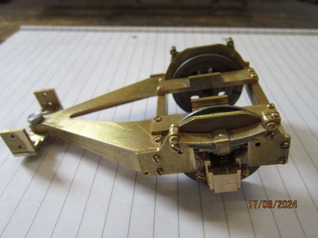
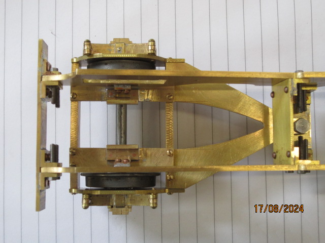
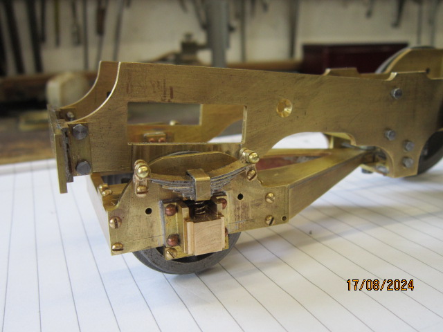
August 2024 - I have finally completed the Beissel Truck for my little loco, the drawings took some time to do especially when being distracted at this time of year by gardening etc. Also I wanted to model the original suspension which is by axle boxes supported by leaf springs with the truck resting on some brackets off the main chassis with side restriction angles to limit the movement. The pictures show how this has been done. The leaf springs are dummies made from boiler band strips of brass soldered together with hidden coil springs providing the springing to the axle boxes. The next task is the cylinders which I will make from bronze bar but I need to sort out the geometry for the valve gear first to make sure I do not have problems further down the line. Because I have turned the valve faces through 90 degrees the angle of inclination of the valve rod is different to that of the piston rod so having done some basic geometry drawings I am making a wooden model of the gear to see if the theory actually works out.
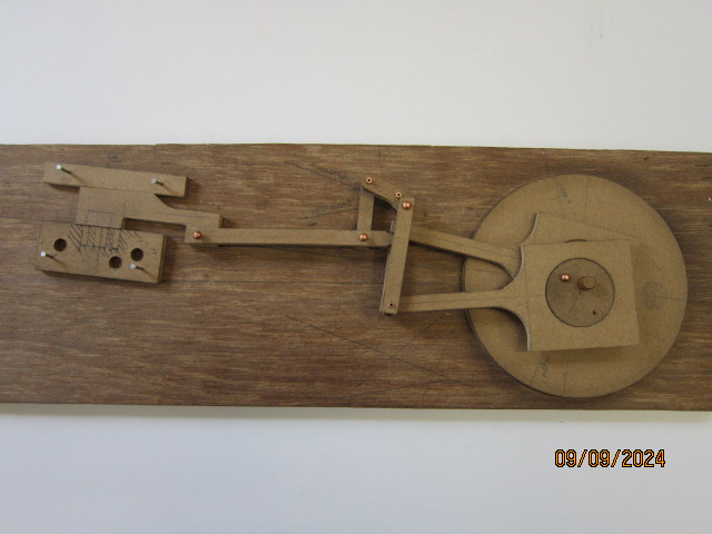
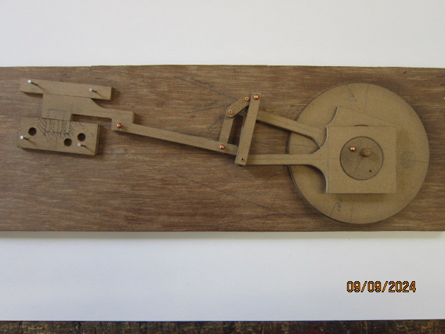
September 2024 - Thanks to some original factory drawings, I have sorted out the model of the valve gear and all seems to work okay, at least within the accuracy achieved using MDF. Below are two pictures of it made in MDF to the full size loco dimensions scaled to 15mm to the foot and built twice scale size. The one shown is my second attempt with much drawing and scratching of the head in between. The pictures show the gear at dead centre in full forward and full reverse positions. Because I have turned the valve face to a horizontal plane the valve rod is 3/16 inch higher than the centre line of the cylinder but putting a step in the valve rod all seems to work out okay. I am now confident enough to start the cylinders, which are to be carved out of 1¾ inch bronze bar.
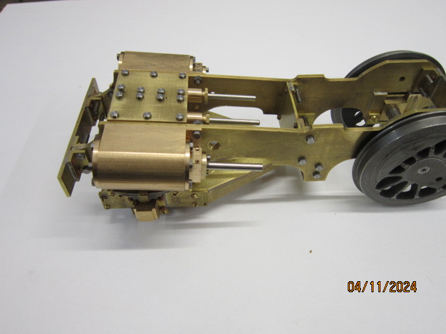
November 2024 - The cylinders are now complete along with the steam chests, valves etc. Not got the inlet or exhaust done because I want to see where best to do them in relation to the boiler and smokebox. Back to the drawing board now after I decide what to have a go at next.
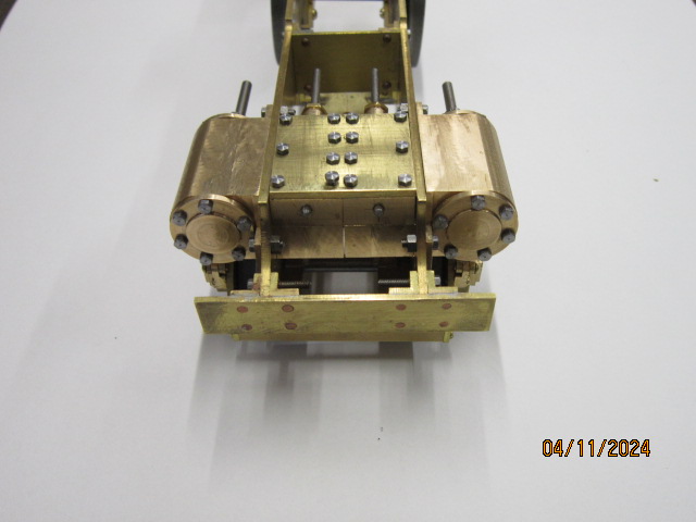
March 2025 - Having finished the chassis and cylinders prior to the onset of winter, I wanted to do the drawings for the valve gear and coupling rods ready for the warmer weather to come along, thinking these would take me most of winter to complete, but had done them by the end of November and unfortunately picked up some of the odd viruses and flue so never got into the workshop. However during my better days I produced the boiler drawings and once the weather warmed up and I kicked off the bugs, decided to make this instead of machining the other parts. The boiler is now complete and I have tested it up 70 psi which would show up any faulty joints and since it is made to conventional gauge 1 standards should pass its pressure test okay. Photos below.
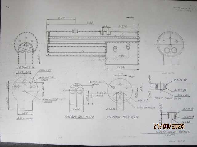
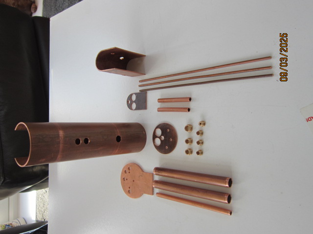
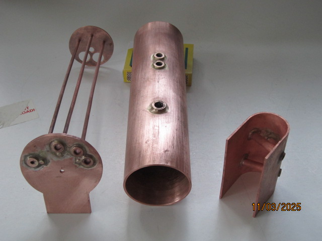
The first is of the drawing that I produced, the second all the various parts to be made. The third is of the first soldering with high melting point silver solder ie. the bushes and solid boiler stays. The forth is the firebox tube plate into the firebox wrapper and the fire tubes into the plate. This was actually done in two stages, I did try to do it in one go but it all moved and had to start again, lesson learned. The fifth photo is of the firebox assembly soldered into the boiler barrel, this joint had to be done twice since I was so afraid of melting the tube plate joint concentrated the torch to much onto the barrel which heated enough for all the solder to run down away from the joint. The second attempt sorted it out. The sixth is of the backhead fastened to the barrel and firebox with the next being the final soldering of the front tubeplate into the barrel and attached to the tubes and solid stays. This I also had to do twice because on the first attempt the barrel and stay joints were good but the tubes did not heat enough and the solder did not stick at all. Reflux, new solder rings, heat up again and all well. I have shown the next one because it is a relatively simply way to at least check the joints without having a full pressure test rig providing you have another loco with a hand pump fitted also using the pressure gauge from the donor loco. This is the tender from my C Class. Lastly the completed boiler with all the surplus material trimmed off.
Hopefully if any less experienced members see this it will show how quite simply these little boilers are provided you take each step at a time, make sure it is right and move on to the next. The material for this boiler was about £100 and lapsed time about three weeks so a mistake is not to costly in money or time but can save a lot against purchasing one and will give a good deal of satisfaction.
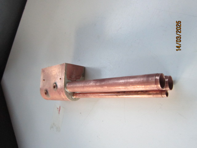
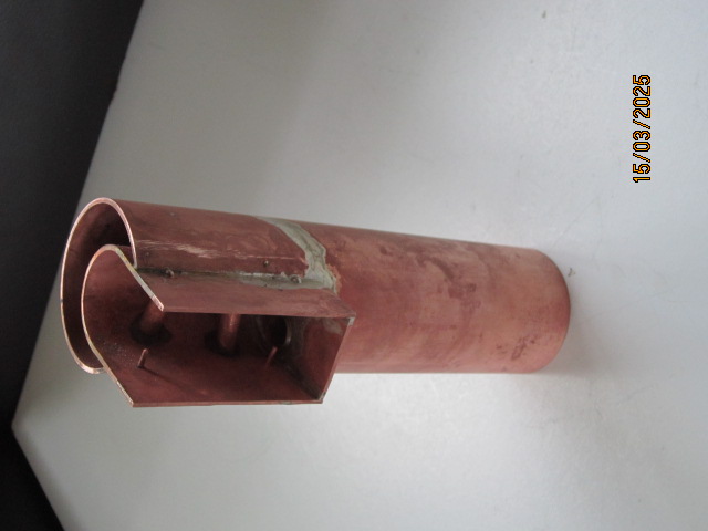
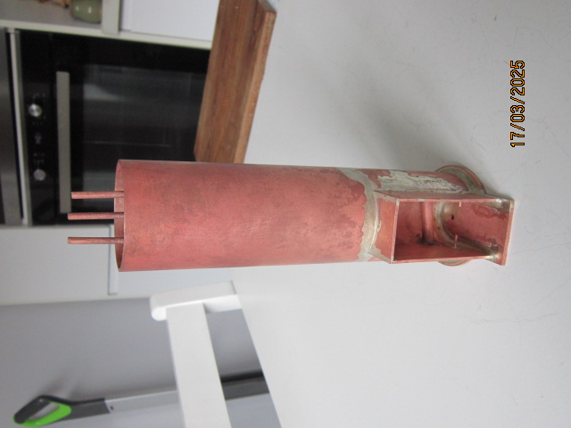
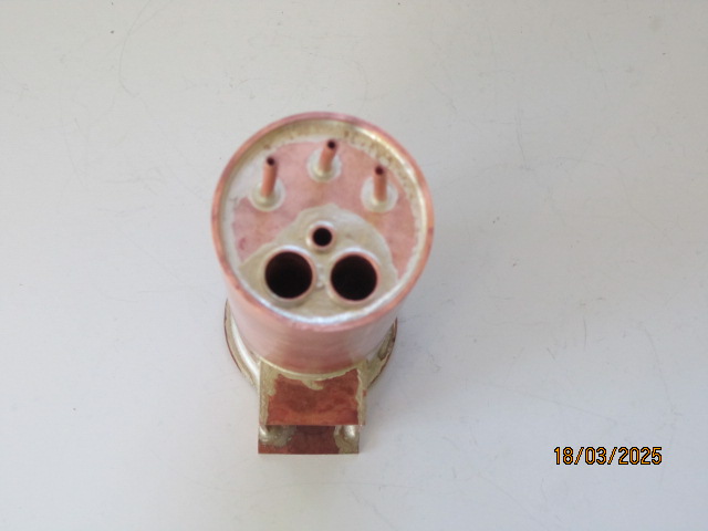
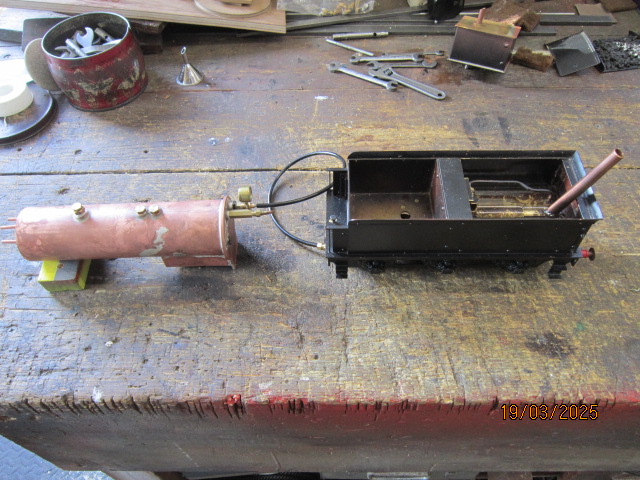
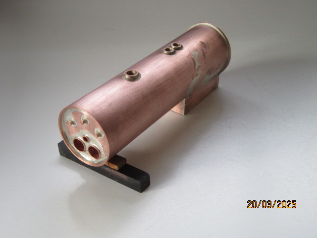
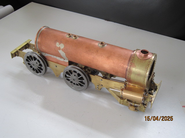
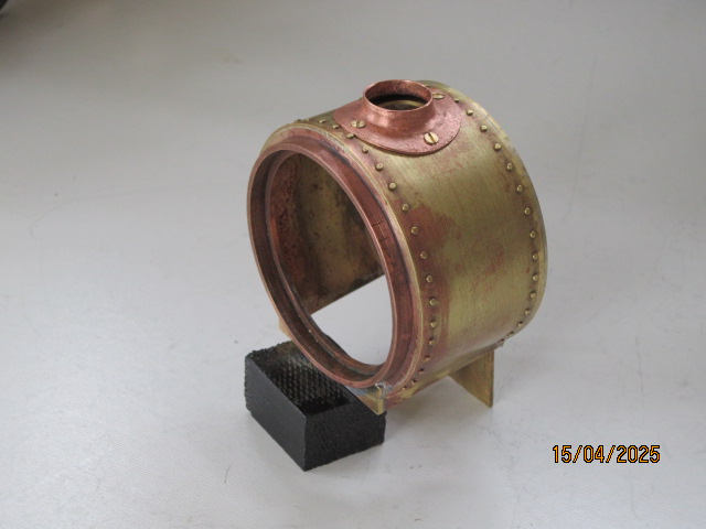
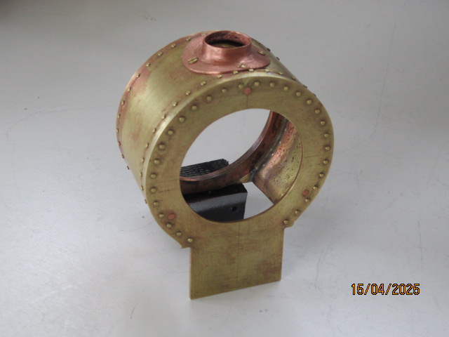
April 2025 - I have now made the smokebox and assembled the boiler in position on the chassis. The smokebox on this early loco is somewhat different to the standard in that it does not sit on a saddle as with most locos, the front and rear plates extend down and are attached to the cylinders and the sides are flanged down to attach to angles also fastened to the cylinders. Not all these attachments are required at this size but for scale appearance need to look like they do. The rear plate is turned from a piece of gunmetal which I found in the scrap box and the rest is from sheet, all silver soldered together. The mount for the chimney is beaten copper sheet using a little former made from steel. The pictures below are self explanatory and include the sketch type drawing I did for it.
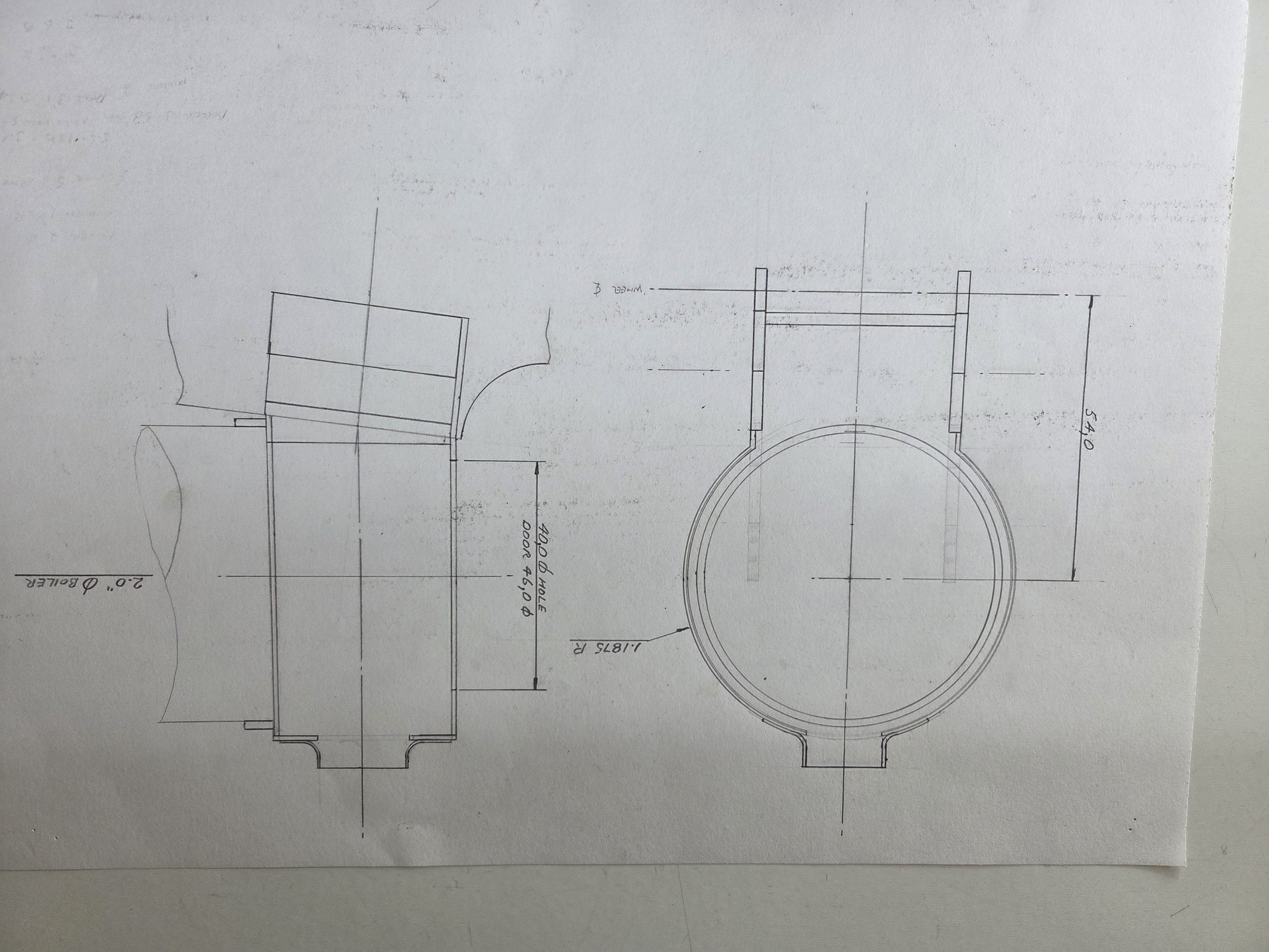
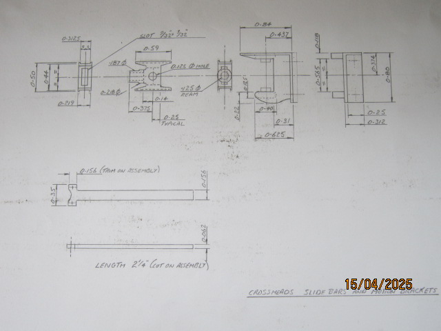
April 2025 - I now for a change am going to make the motion brackets, slide bars and crossheads so I include the drawing I did for these items. How long it will take will depend on the weather and how much gardening is able to be done.
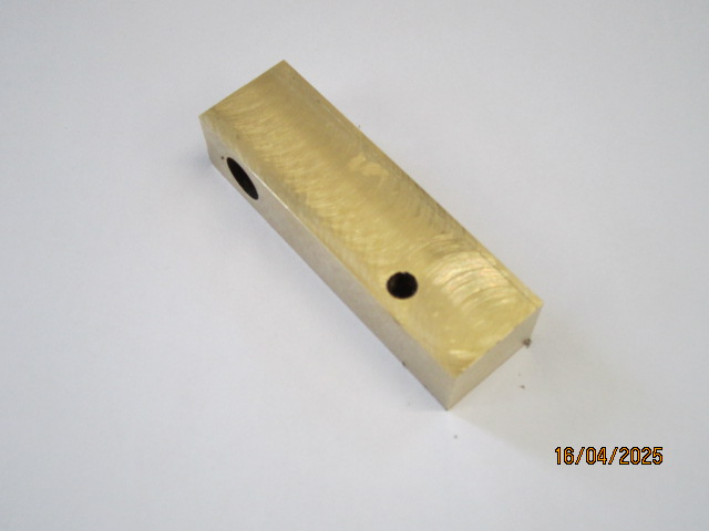
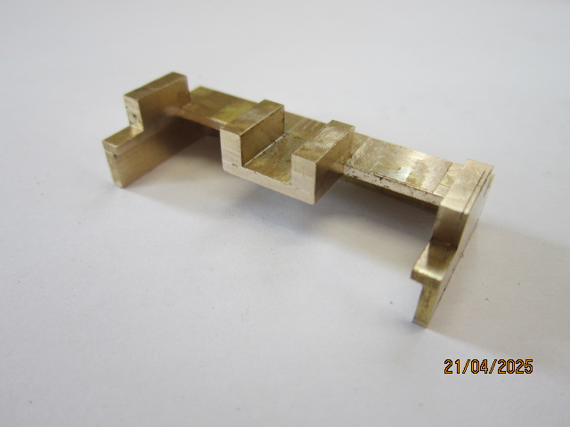
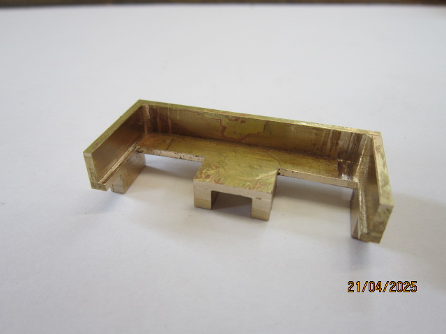
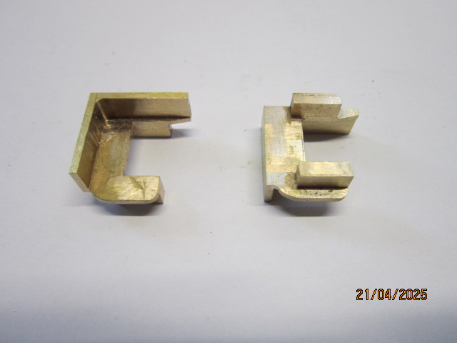
April 2025 - Despite having a few days on the IOM and doing the gardening, I have made the motion brackets. The pictures show the basic steps taken, ie. found a piece of bar that both items would come out of despite having two holes in it. The advantages were that in doing both at the same time all the dimensions would match and also guarantee hand and opposite manufacture. However in trying to make sure the holes would be in the surplus material I underestimated the overall length to allow for splitting when complete so instead of the lower lugs being one piece with the bar I had to extend the length and these lugs had to be sacrificed by machining off and a new piece silver soldered on during manufacture, once finished you cannot tell the difference.
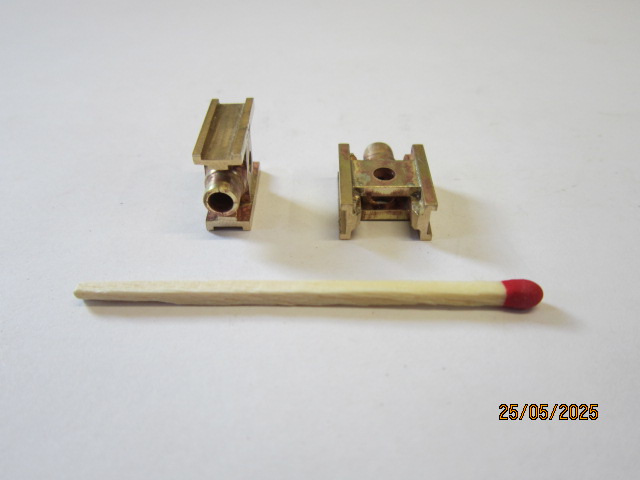
May 2025 - I have completed the crossheads for my little loco and the photos are below. The drawing I did was based on the works drawing which appear to be made from a single forging but when I examine the photos of the loco the ones fitted appear to be a forging for the centre with the sliders separate and then welded on so these are the ones represented by my items. The centre which includes the mountings for the connecting and piston rods were machined first which enabled the slot for the connecting rod to be done and then separate slide pieces were machined oversize, silver soldered in place and then finished as a full assembly. They are not far off scale appearance so quite pleased with them. It really is a bit like watch making, just look at the standard match to get an idea of the actual size.
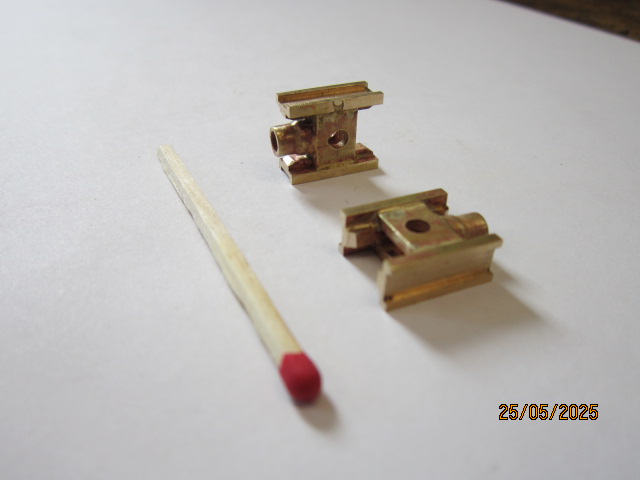
June 2025 - Below are the latest photos of my progress so far on my little engine. They show the crossheads, motion brackets, slide bars, connecting rods and coupling rods. There is still some polishing to do and bushes to make and fit, but I will do that when all other items to do with the workings have been made. Now for the valve gear eccentrics, linkages, valve rods etc. starting with the eccentric followers. I have drawn all these parts, in theory anyway, but not yet thought about how to make them. So, it might be some time before my next pics.