5 inch 9F by Peter Willox
Click on any photo to see the full size version
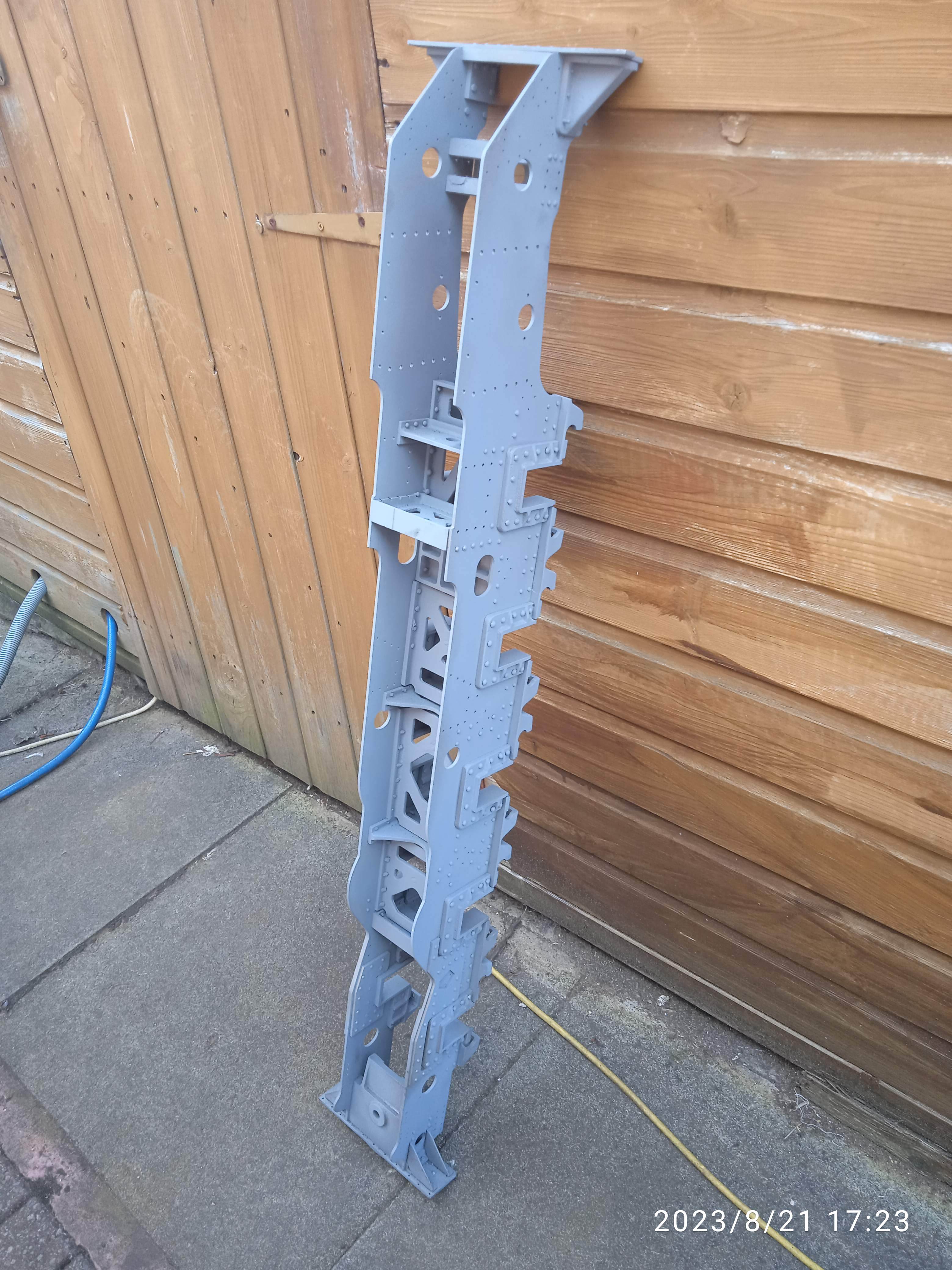
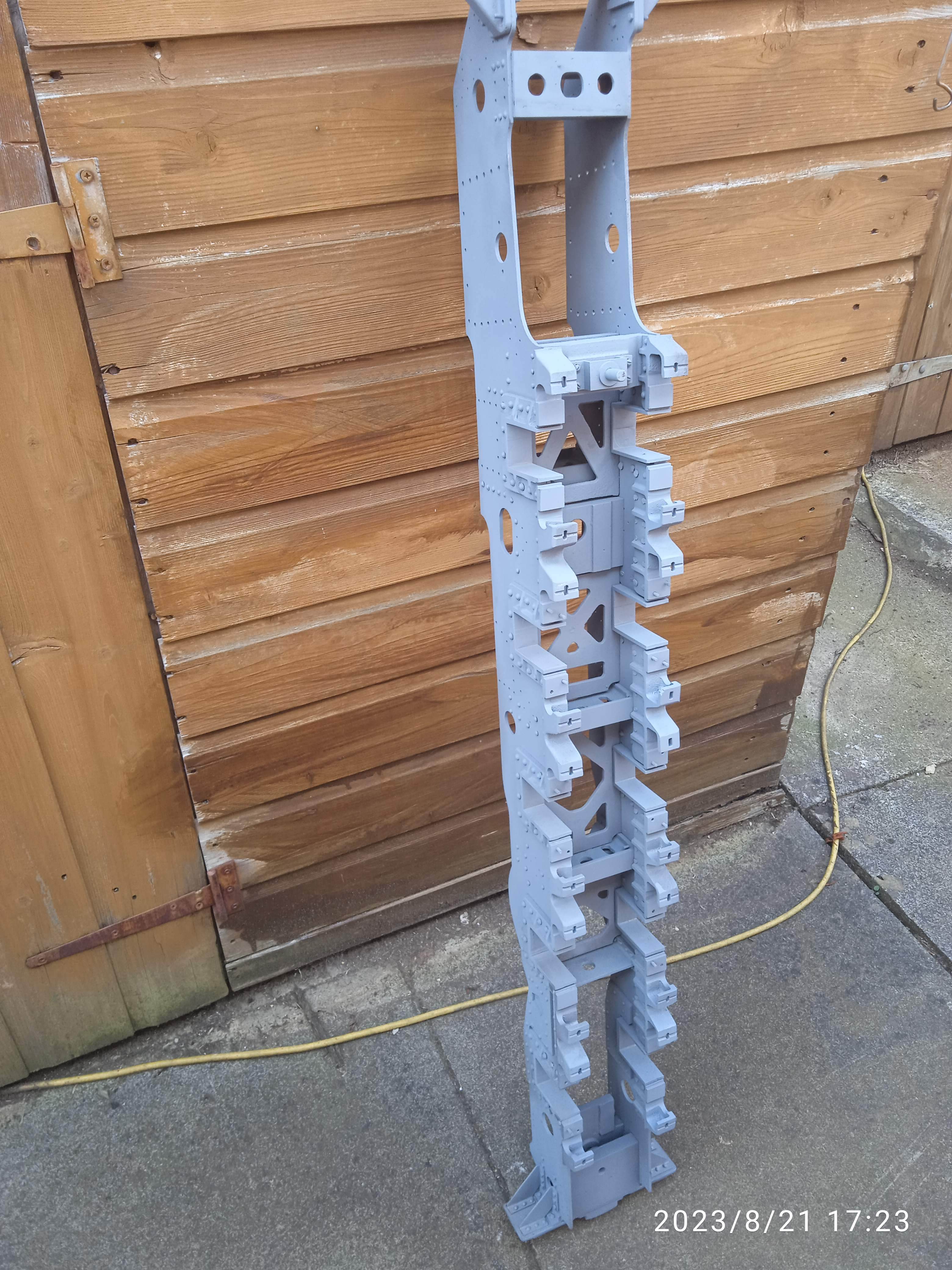
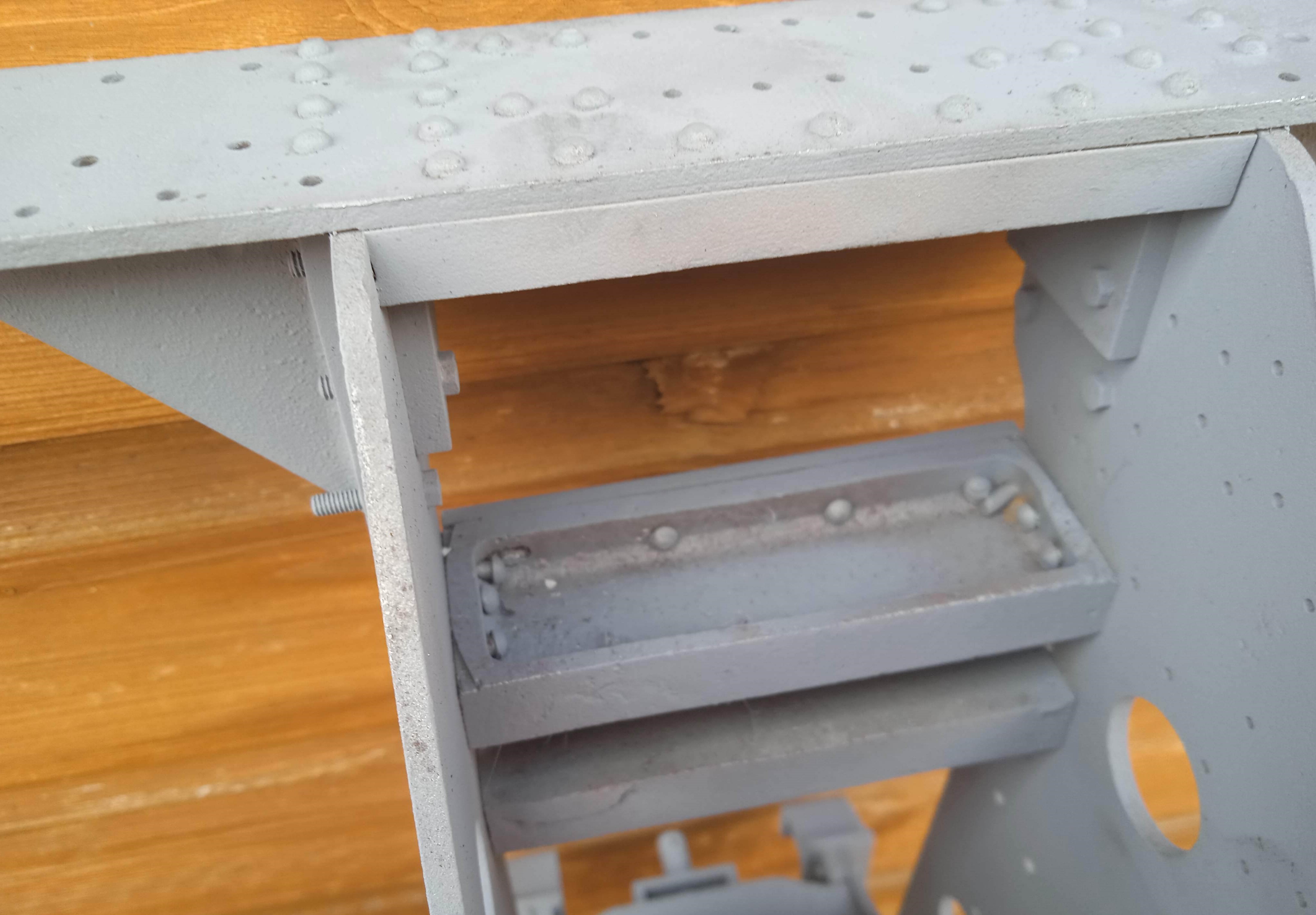
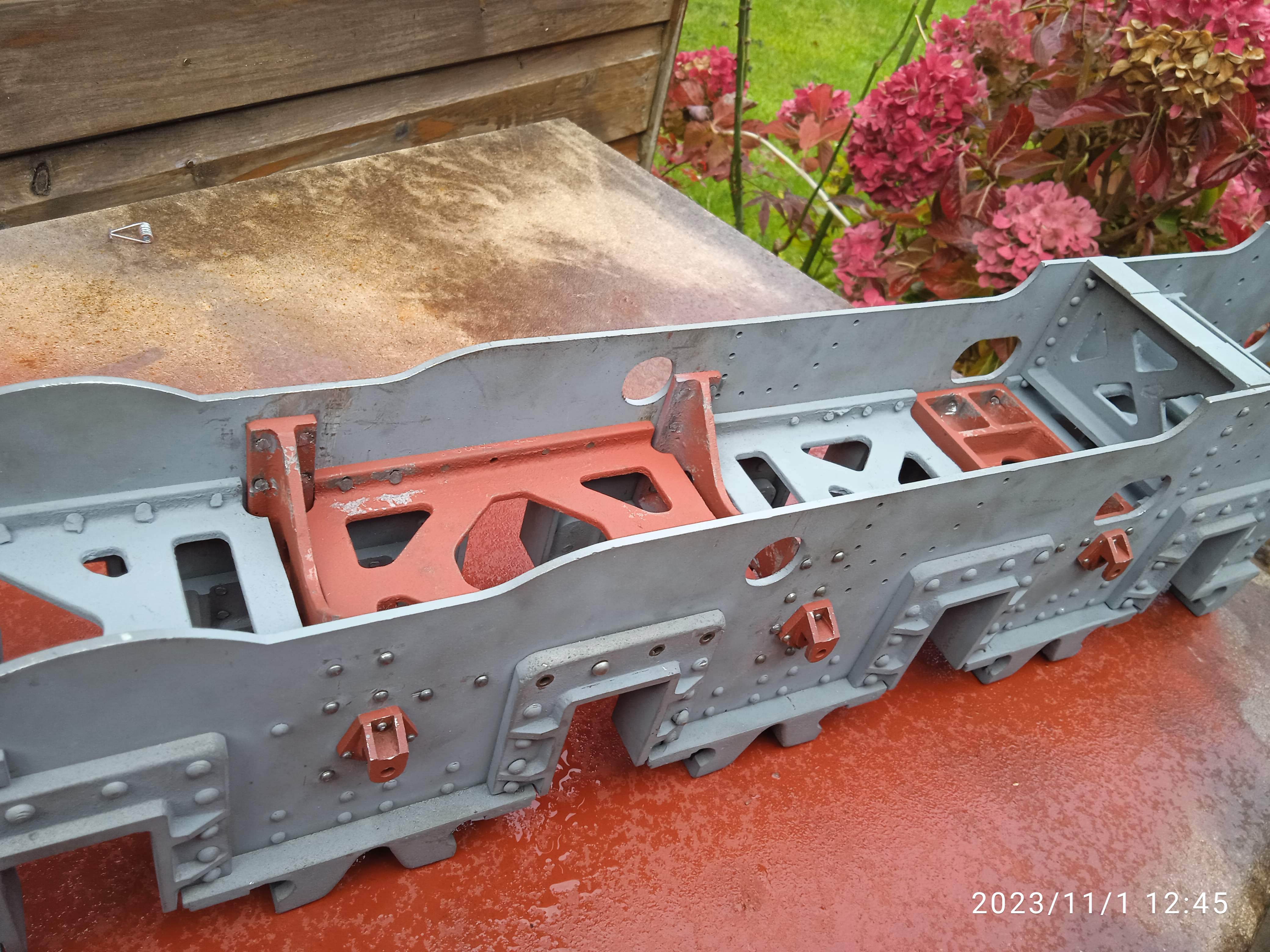
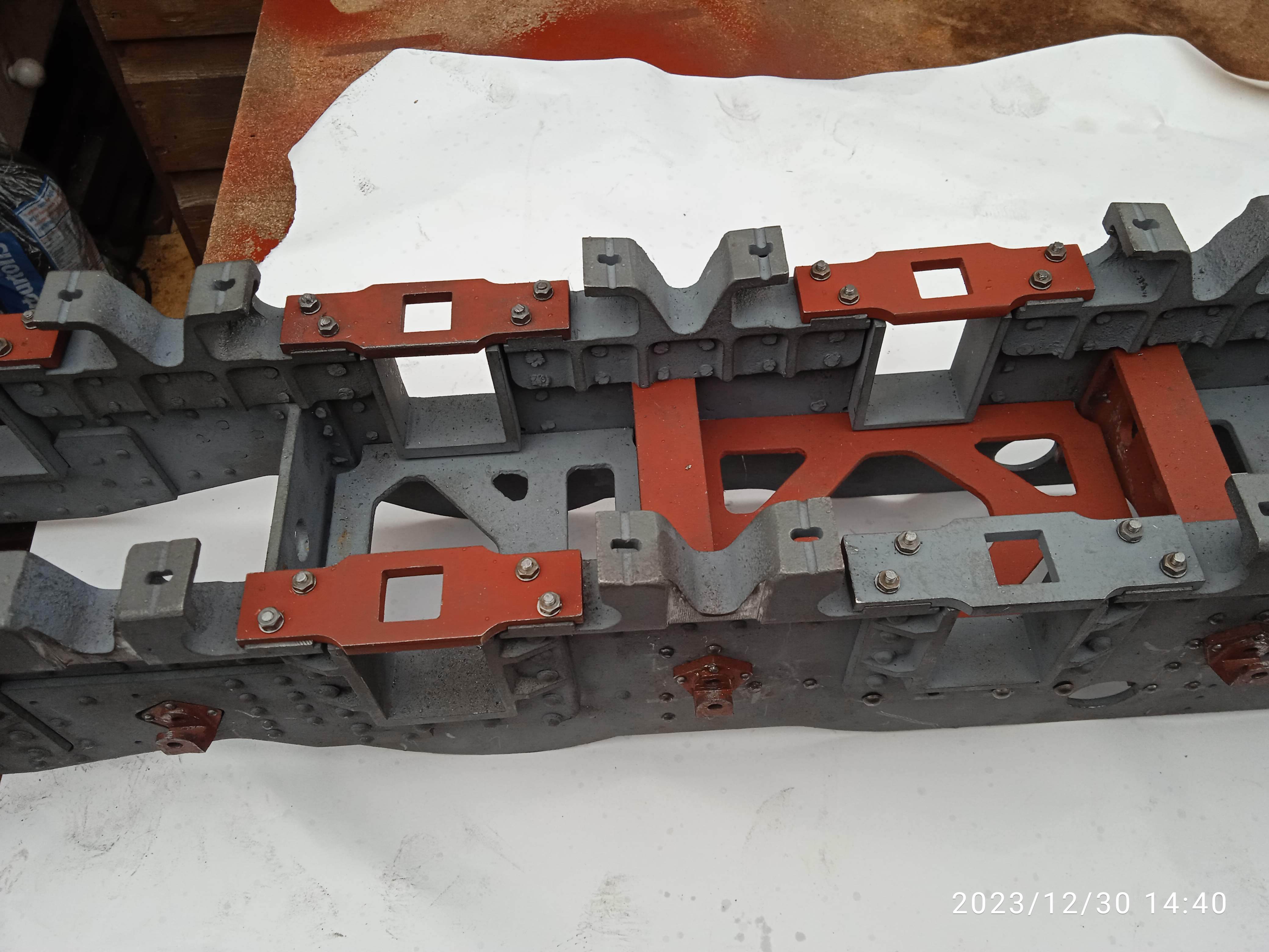
It’s not like I need another project, but when Ben posted if anyone wanted a complete set of 9F castings with the main frames already assembled, I couldn’t resist. One day I might actually finish something! The first few photos show the chassis after having it cleaned and sprayed in grey primer. They are very well made, square and parallel, the only fault being the pony truck stretchers where the rivets foul each other. I might remove the stretcher, clean up the inside and re-rivet, but as it can’t be seen there’s no harm in leaving it as is.
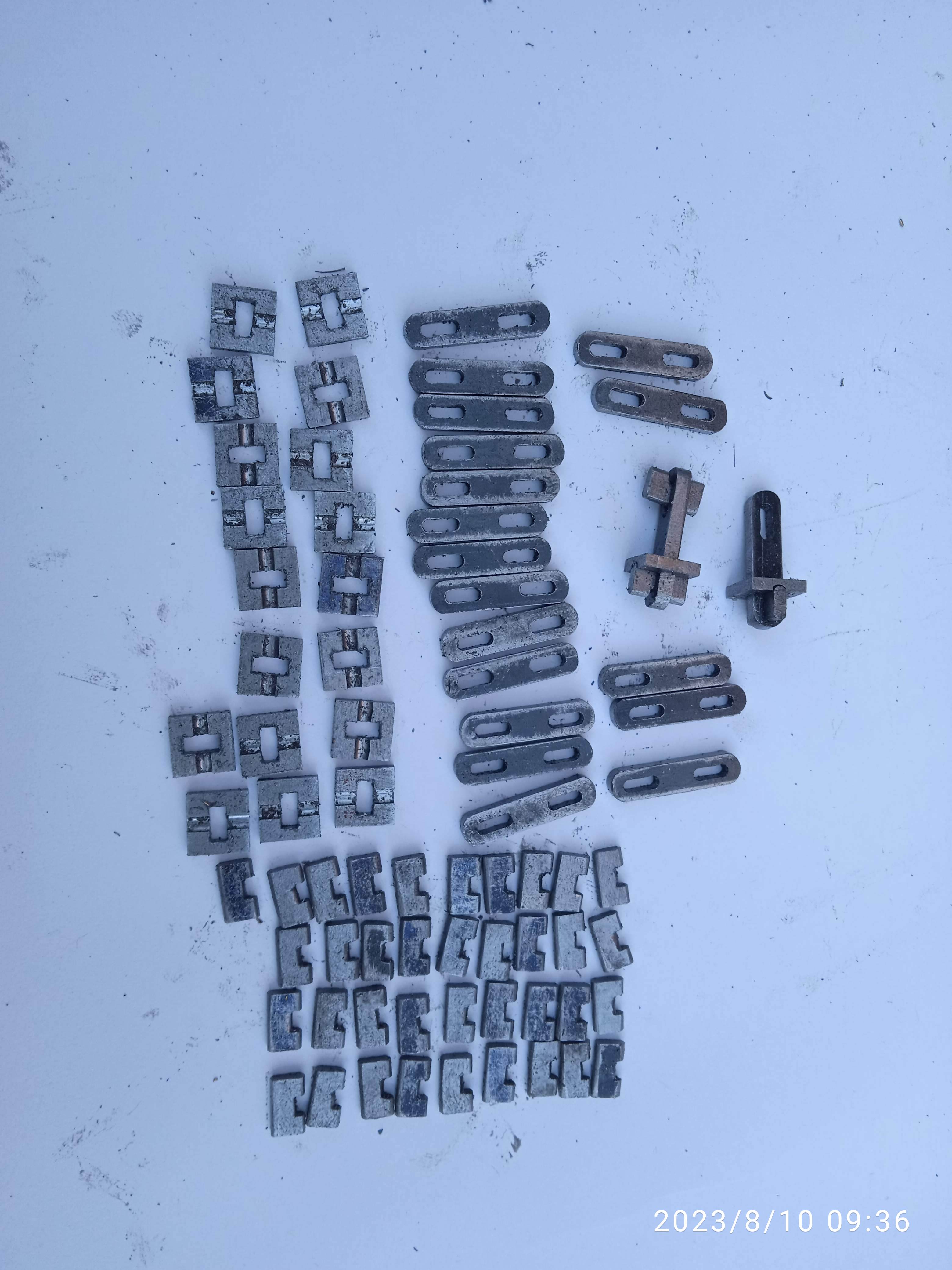
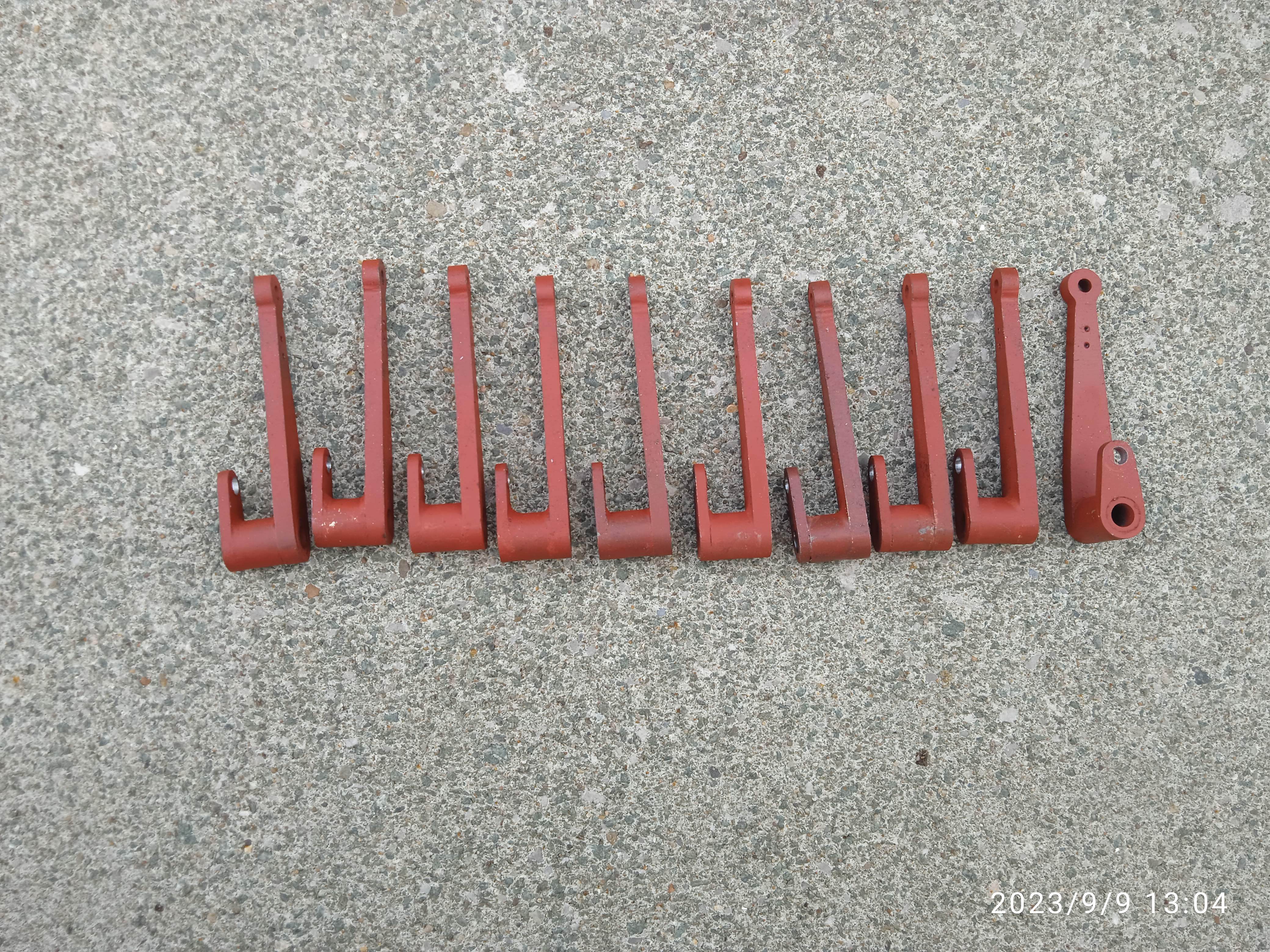
With 10 wheels there are a lot of brake and spring components, so I thought I would ‘bash’ some of these out. 40 cotters, 20 cotter pins and 20 spring links. (The spring hanger brackets had already been assembled on the frames.)
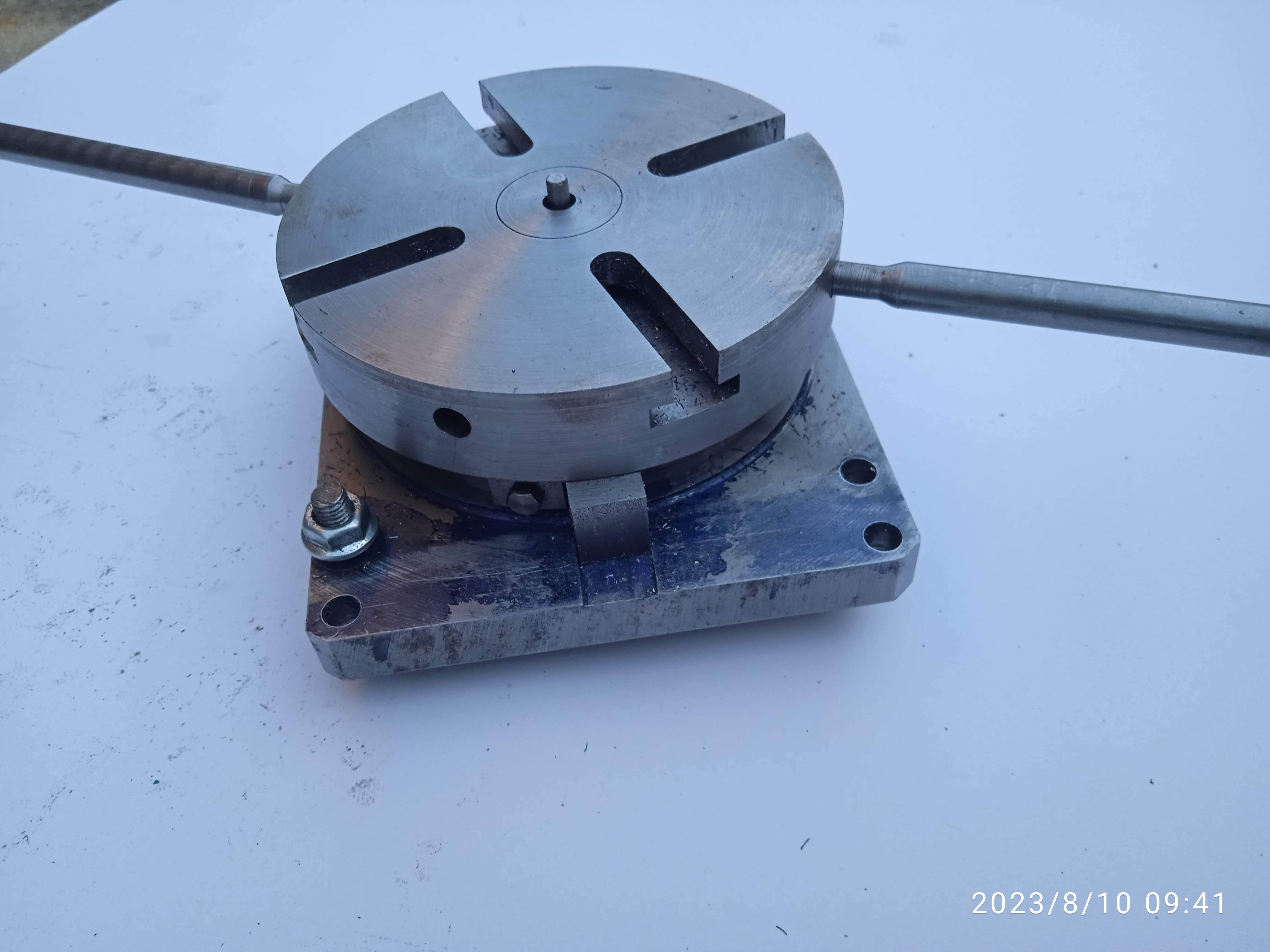
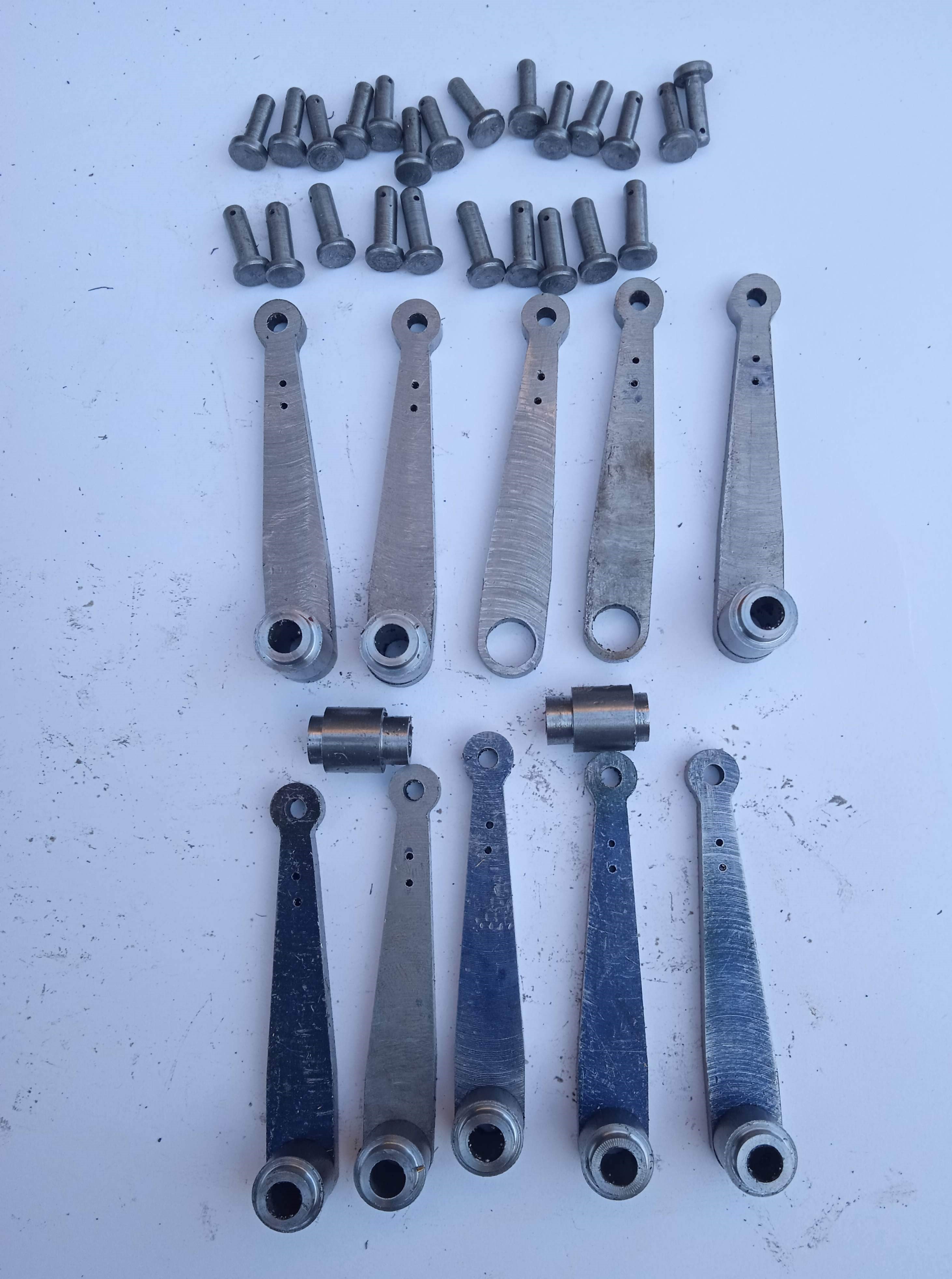
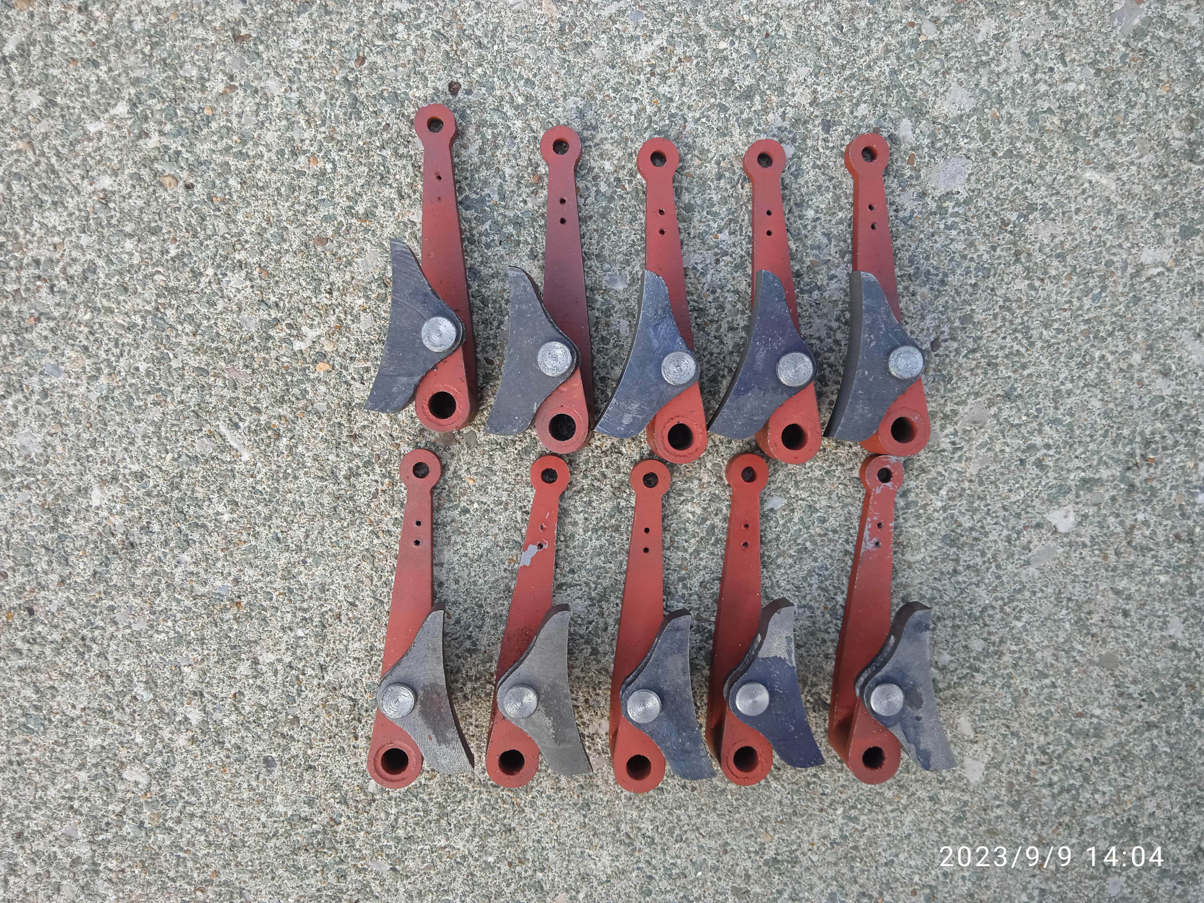
September 2023 - More photos below - With ten brake levers some sort of jig would be needed to profile them. I use a block of metal peppered with M5 holes for such jobs. Once the sides were tapered, the ends were rounded in a George Thomas rotary table I had built. A very useful tool indeed, and one I would not have contemplated making without access to the machine tools in our clubhouse. After making all ten, it was nice to get to do some simple turning in the form of the brake block and arm pins as well as the brake arm pivot bosses. All that needs doing now is to make the short arms and solder all together.
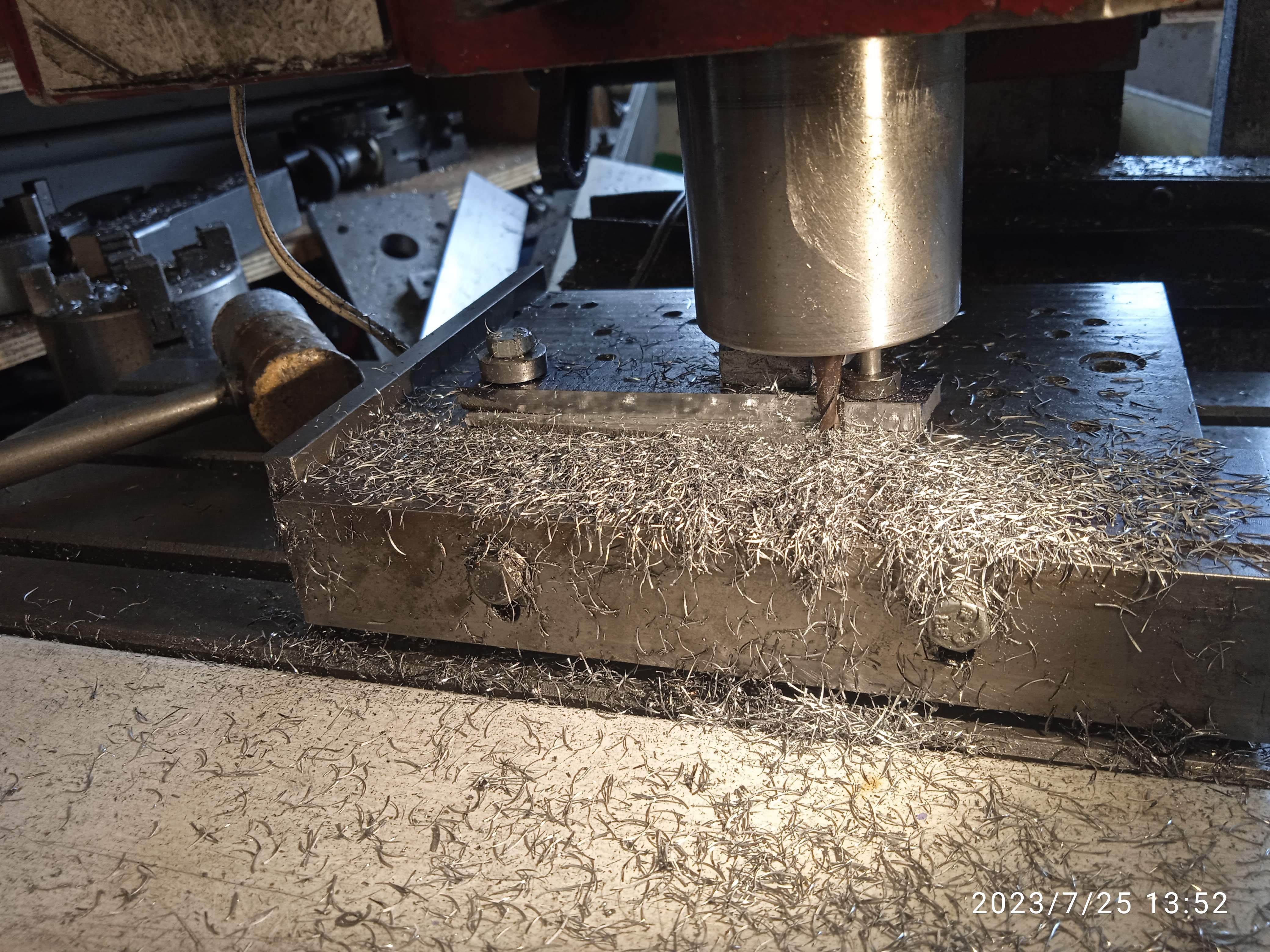
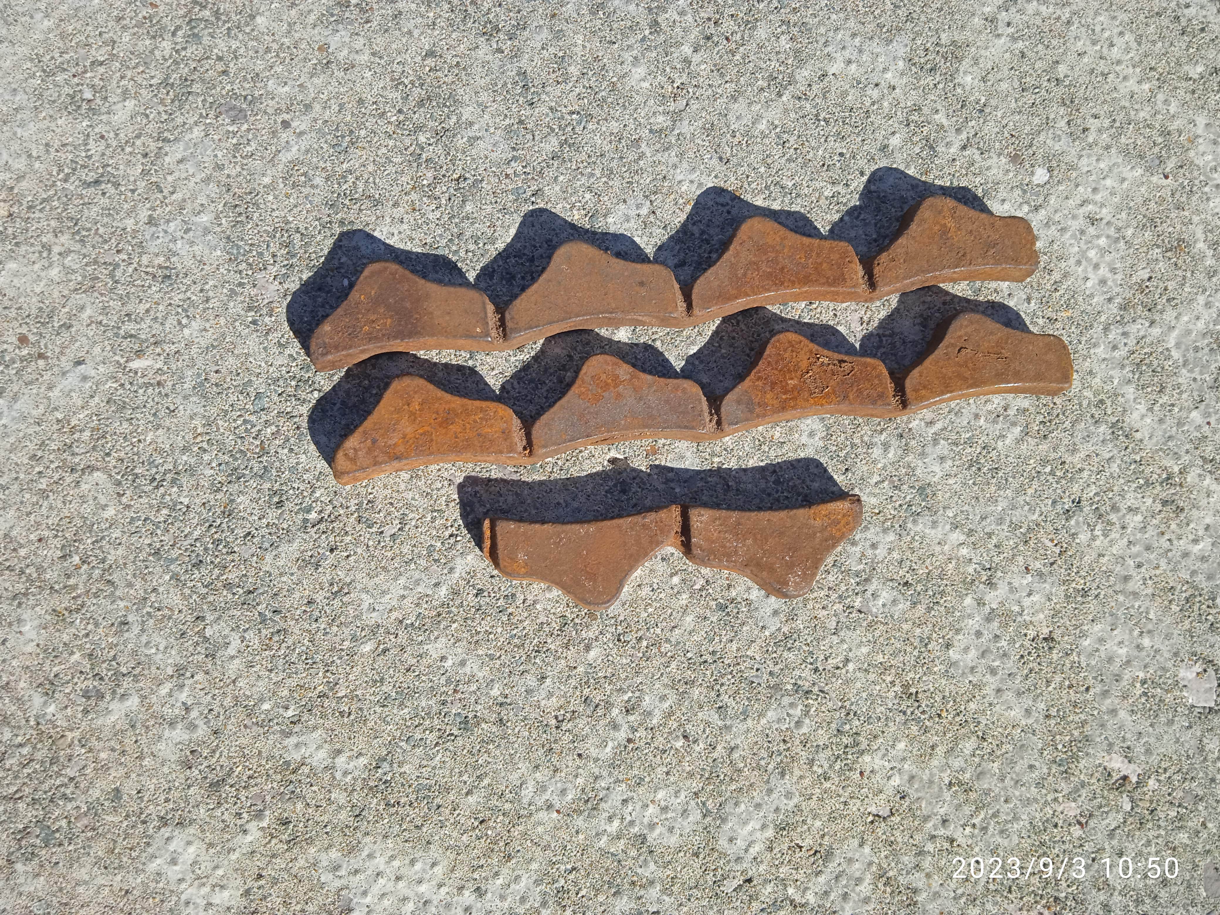
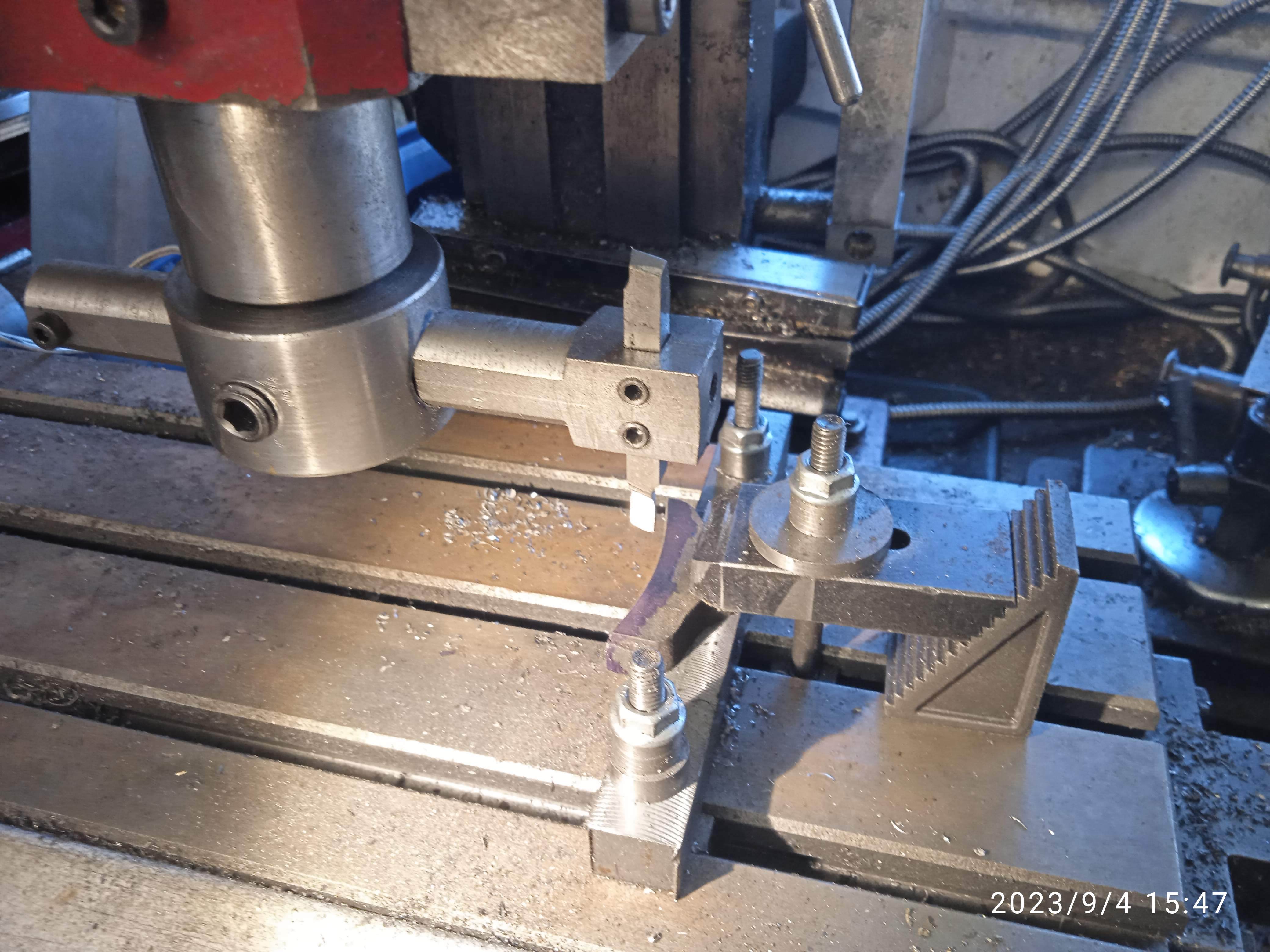
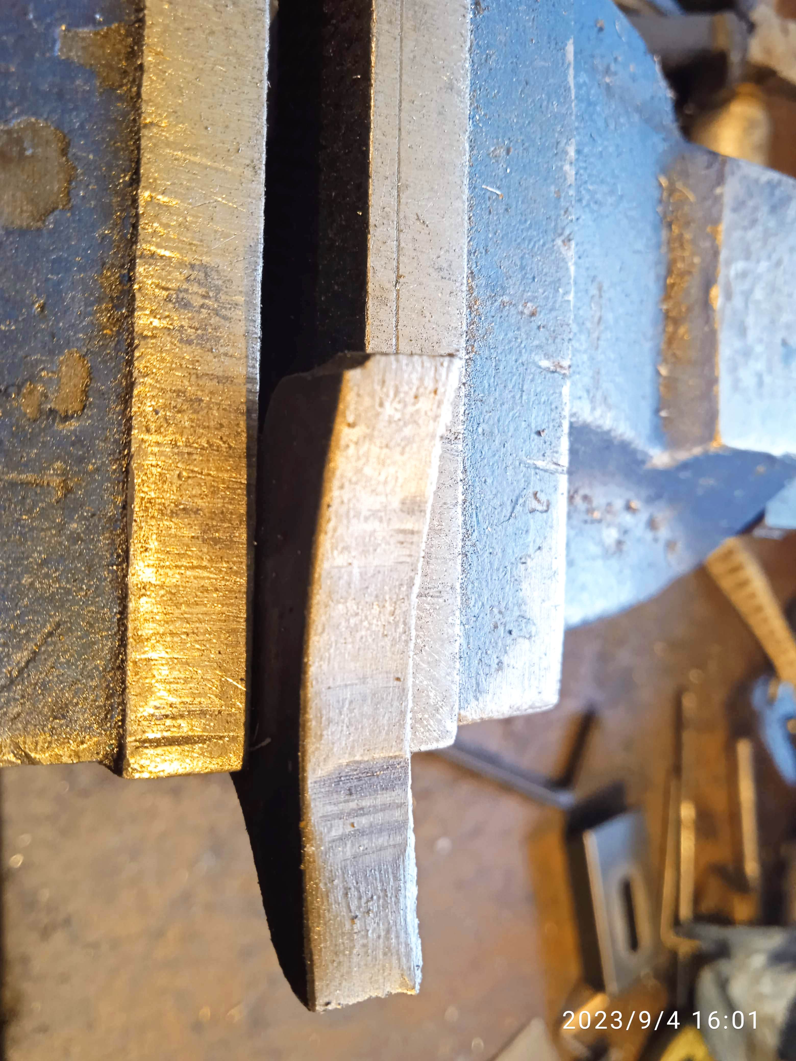
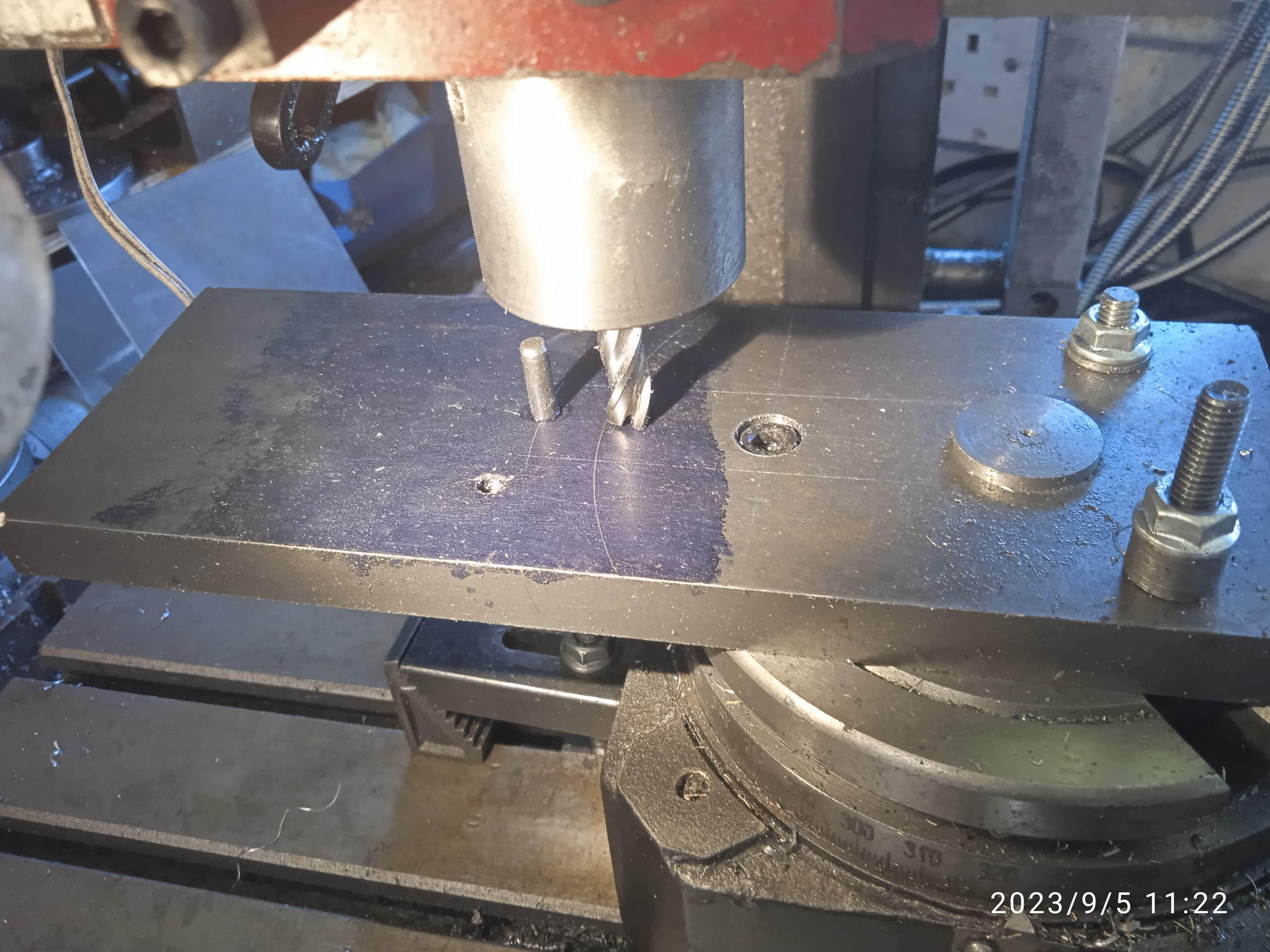
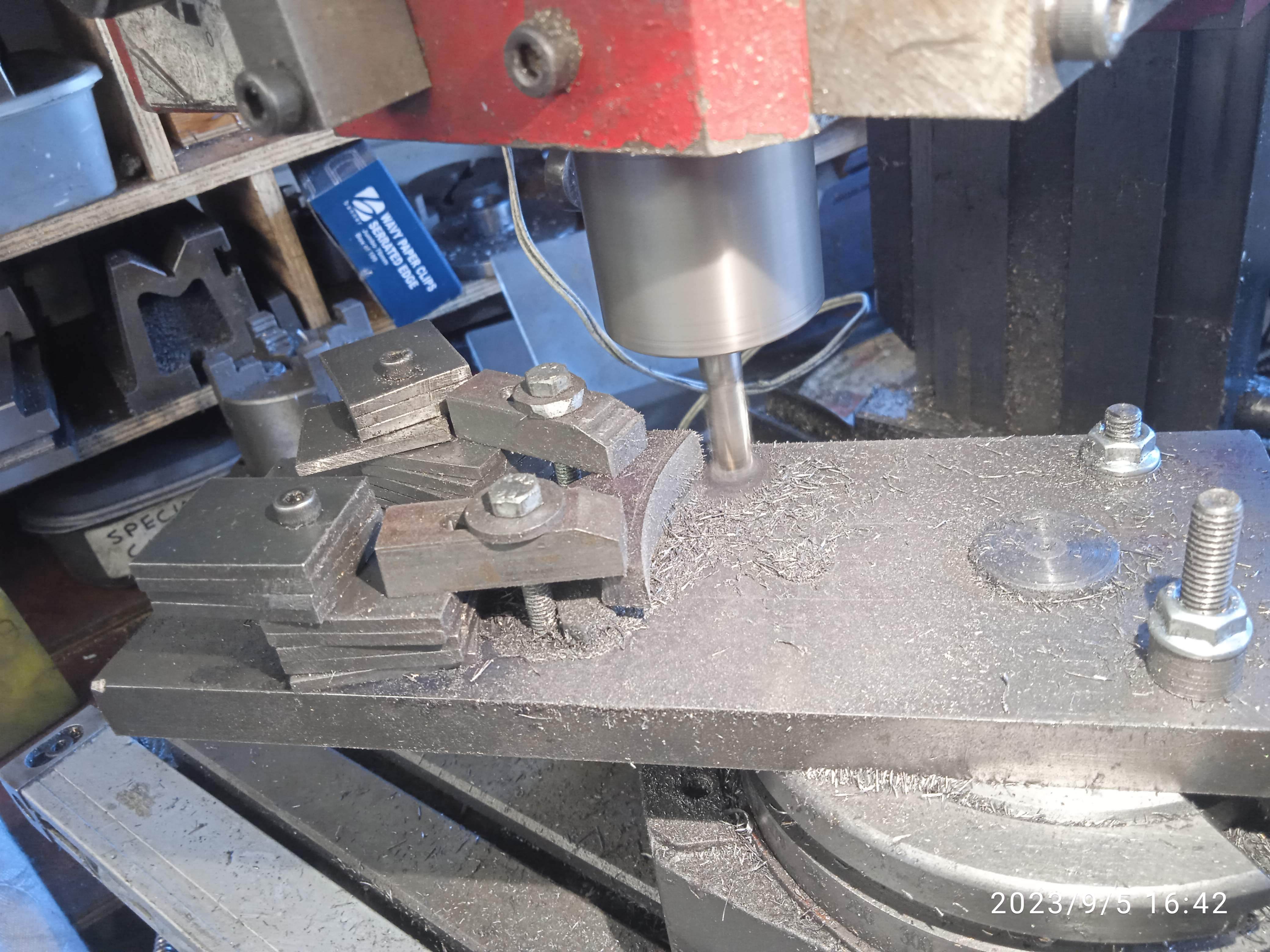
September 2023 - More photos below - Compared to the long arms, the short ones were easy to make. Everything was soon silver soldered together. (photo). I like the way Ben makes his brake blocks from cast iron bar, but as I had the castings (photo) I may as well use them. After drilling the pin holes, I thought I would try using a fly-cutter to produce the curve (photo), but I faced two problems. My milling machine is a light bench-top model and therefor lacked the rigidity required for an interrupted cut at a large radius. It also has a variable speed motor, which meant that if I ran it at a low speed, which the cutter needed, it lacked the power to cut. Increasing the speed just caused the cutter to become blunt quite quickly. The finish left a lot to be desired (photo). Another method was needed. A large piece of flat bar was bolted to my 4-inch rotary table to extend it. The diameter required was scribed and a cutter brought up to the line. (photo) The X-axis was zeroed and then it was a case of bolting each block ( I drilled a hole in the bar and used a peg to locate each block) to the bar and milling the curve.(photo) A far better method. They were soon done and fitted to the brake levers.(photo)
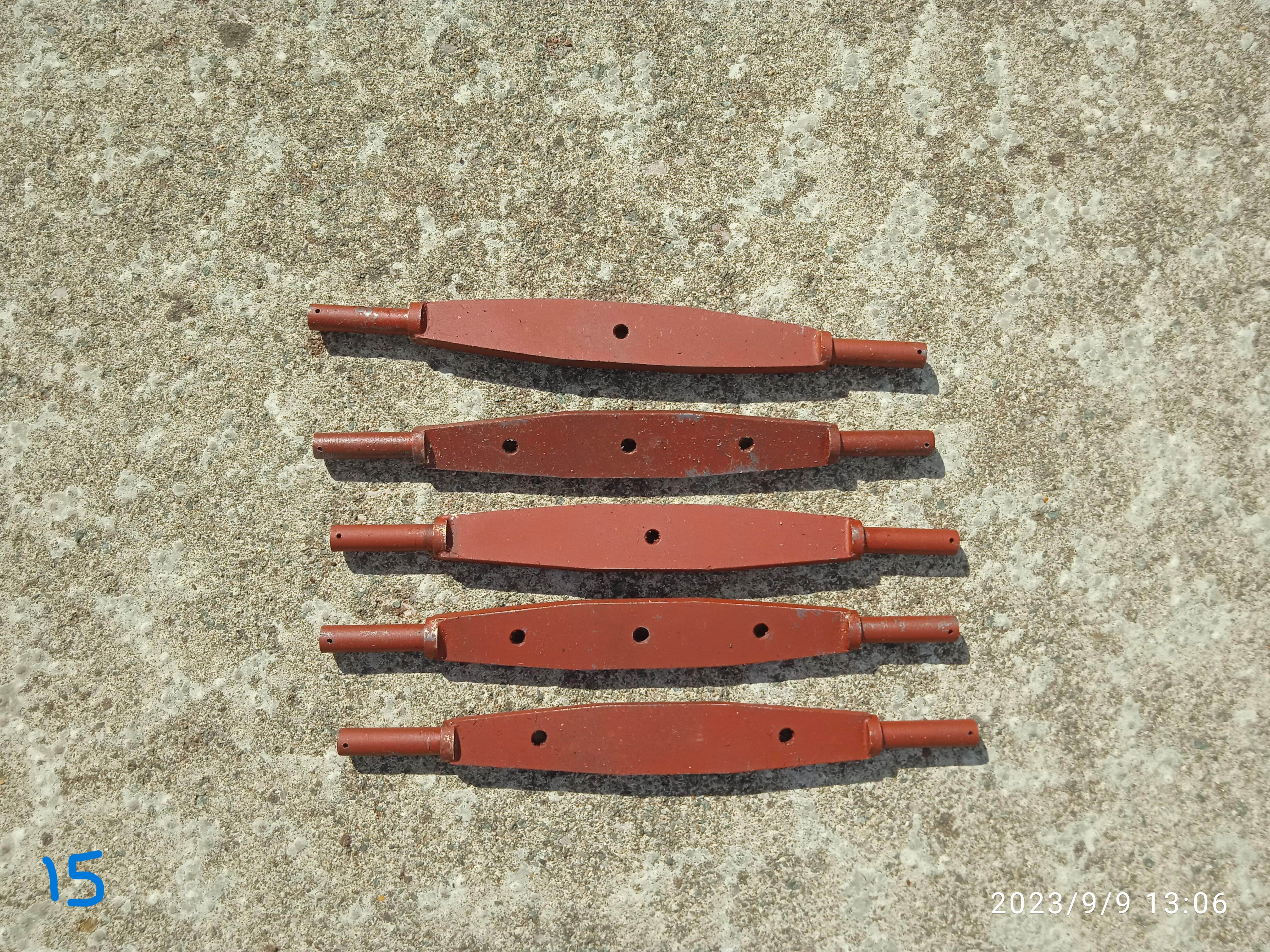
October 2023 - More photos below - The brake beams – at least there are only five of these – were straight forward to make, each consisting of three parts; the main body and two end pieces all silver soldered together. (Photo 15).
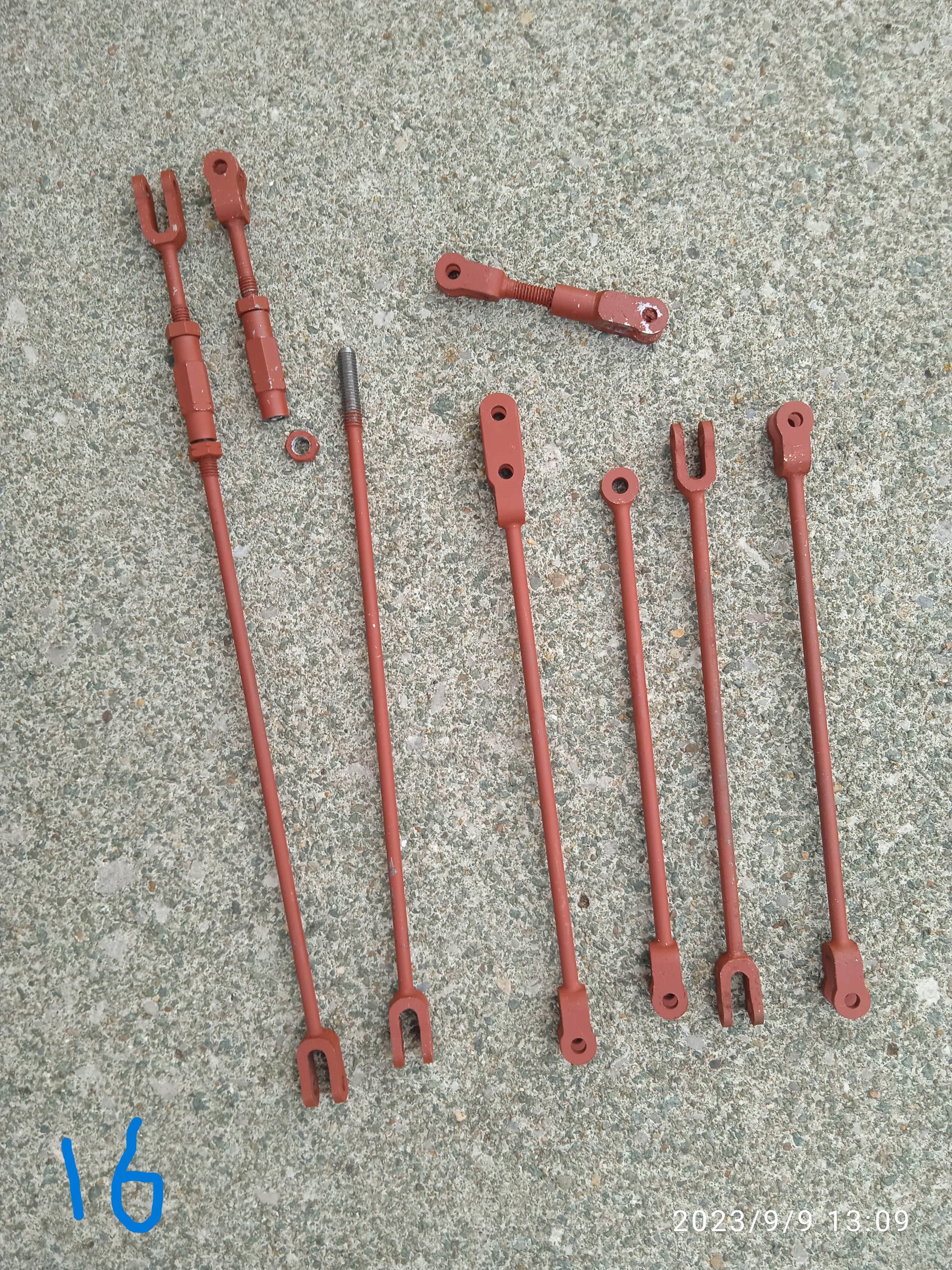
The brake beams were slightly more complicated to make, but at least the hand-operated rotary table made short work of rounding the ends. Although by the time I had finished them and milled all the slots, the 4mm end mill was only really fit for the scrap bin. You might just notice the ‘nicks’ on the hexagon ends of the adjustable rods. This denotes that they are left-hand threads. (Photo 16).
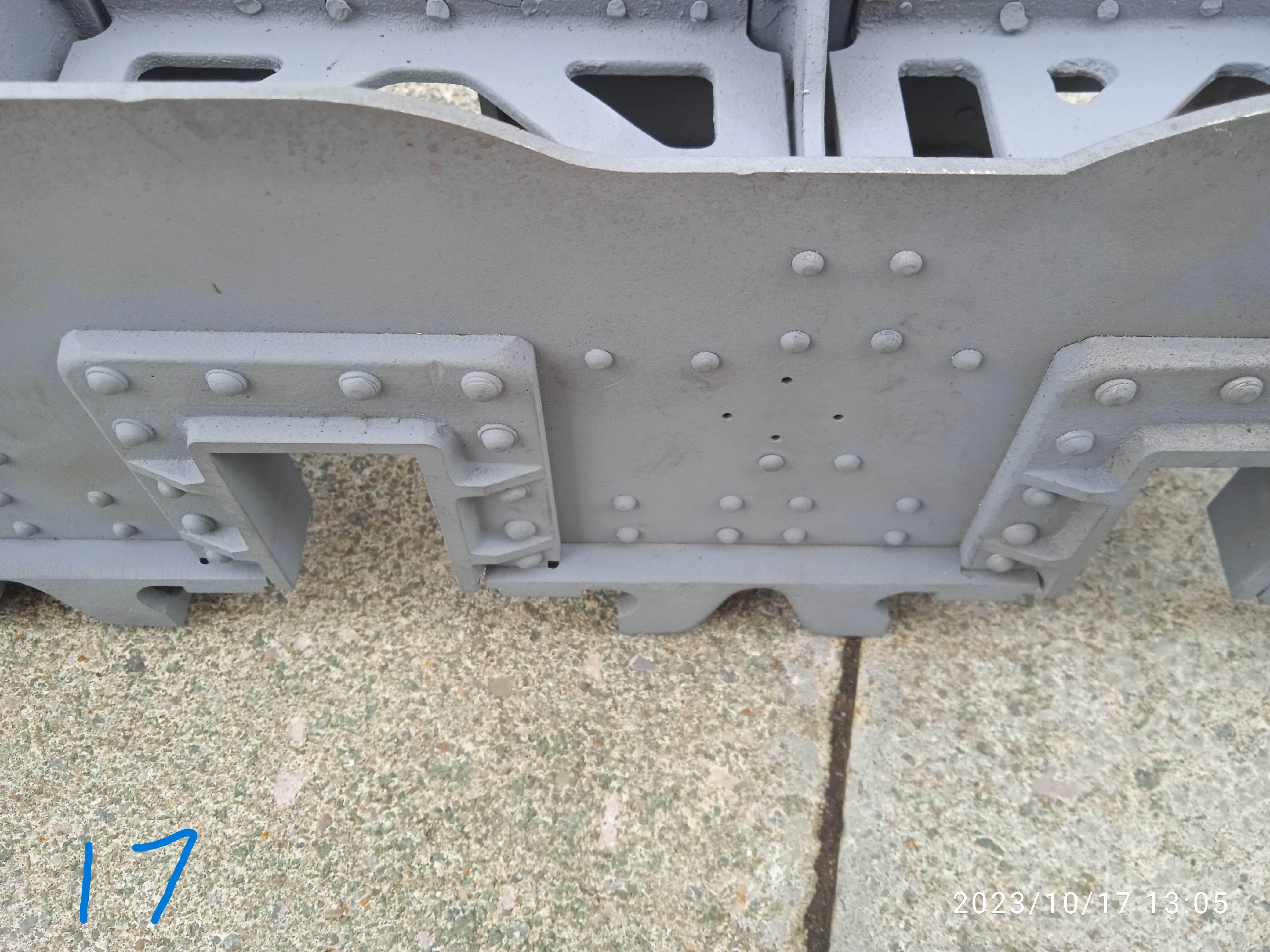
With these parts done, I decided to make the brake hanger brackets. And this is where I ran into my first problems. Although the chassis was well made and square – all the horns were accurately machined and lined up, the original builder had not fitted the brake hanger brackets but had drilled the holes for them. This caused two problems. It was difficult to pick up the holes on the hanger brackets as some of the frame stretchers blocked them, and it would be nigh on impossible to rivet some of them on due to the aforementioned stretchers (Photo 17 – the four small holes are for the brackets with the stretcher blocking some of them). To get round the problem of trying to mark out the holes on the castings, I decided to fabricate them. Photo shows the process used as well as a couple of the original castings. The ‘thick’ back plate is the drill jig I used to drill and profile the plates.
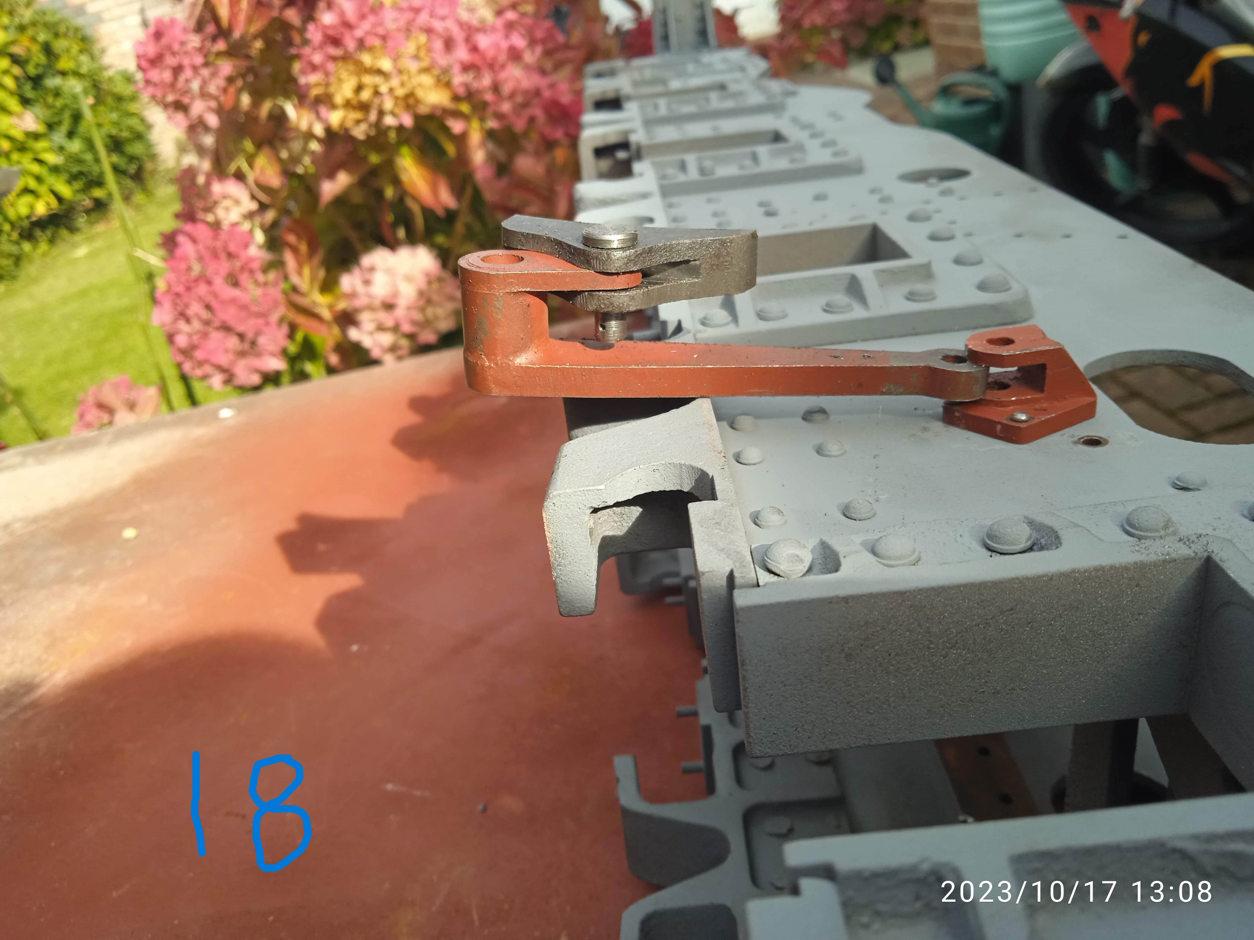
Once I had finished them it was time to start riveting them on, which would mean removing some of the back plates. And then I hit another problem (Photo 18). Something is wrong somewhere. I shall have to comb the articles ( it is to the Les Warnett design serialised in EIM) to see if it is a drawing error or a building error. At least it’s a good excuse to visit the National Railway Museum again!
November 2023- More photos below - Well, it does appear to be a drawing error. but before deciding what to do about the mismatch between the brake hanger brackets and spring hanger brackets, I decided to fit the hanger brackets. The rear brackets were fine, it was the other four that needed some frame stretchers removed. The rivets were chiselled off, the brackets removed and using a Dremel with a ball-nose burr, I was able to 'dimple' the insides of the holes to form the pocket to peen the rivets into. Fortunately, I had a couple of shop made small rivet hammers that I could just use between the frames. Once peened over and filled flush, the frame stretchers were refitted.
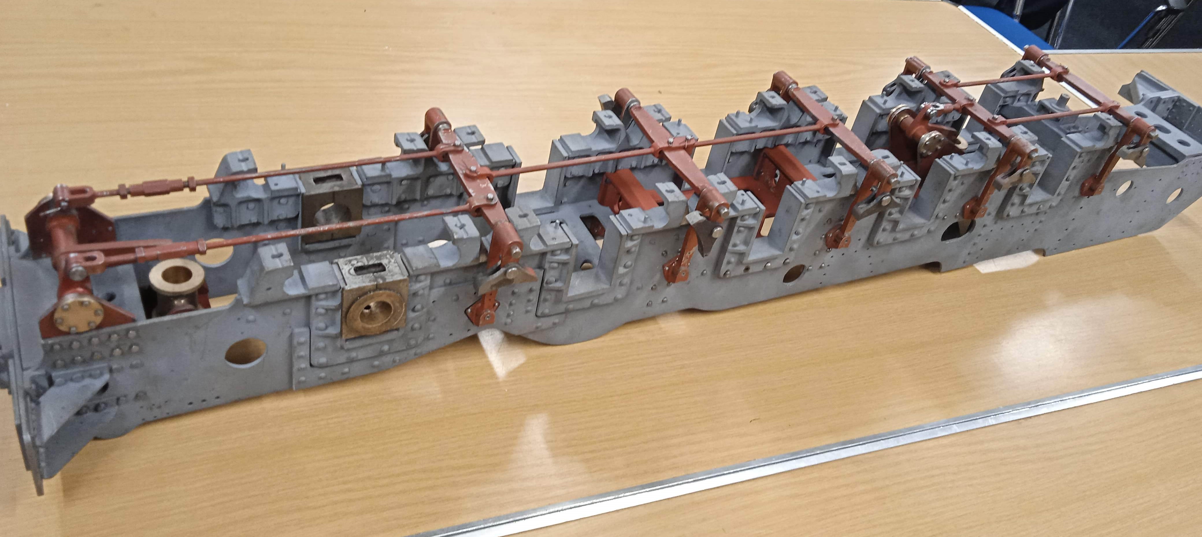
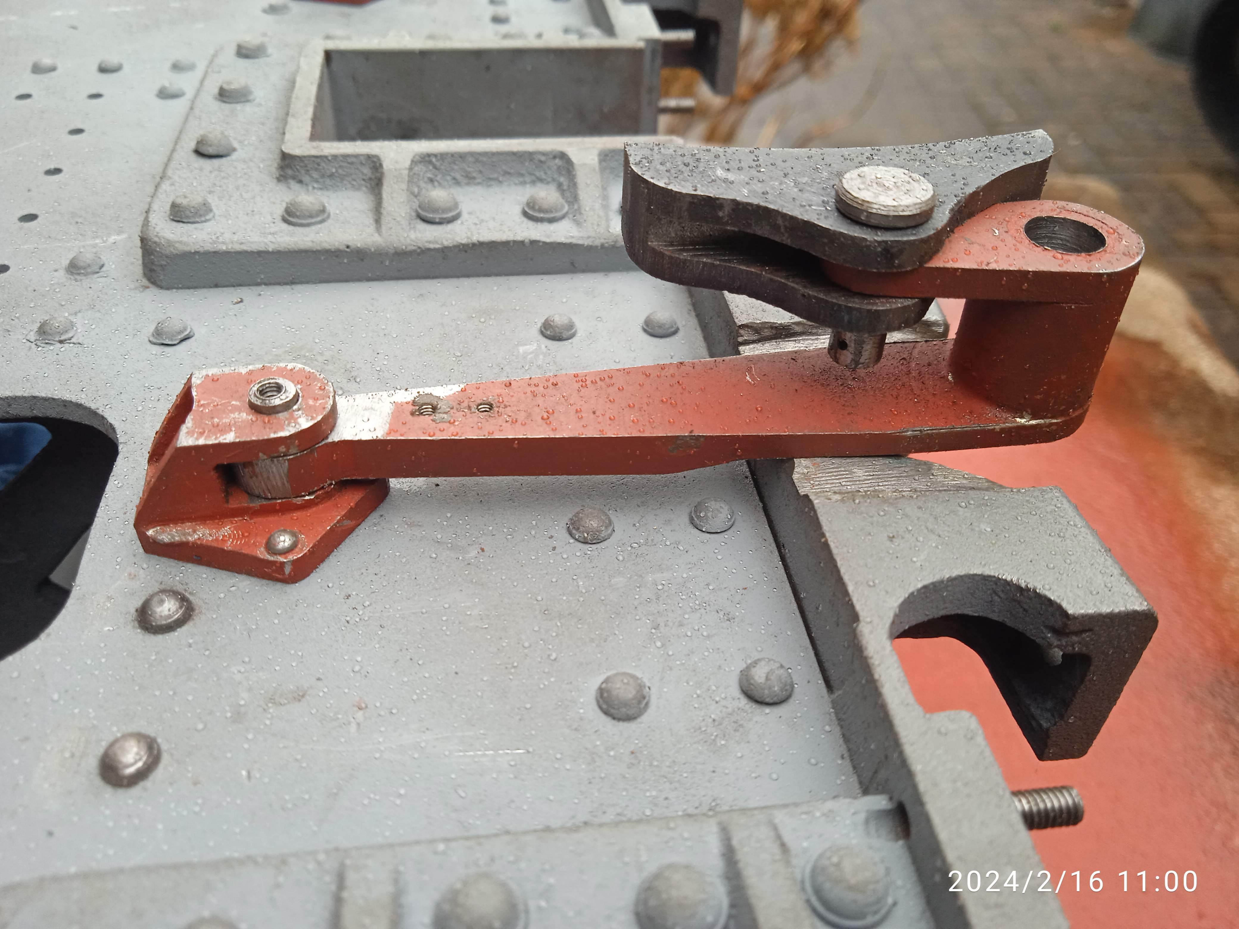
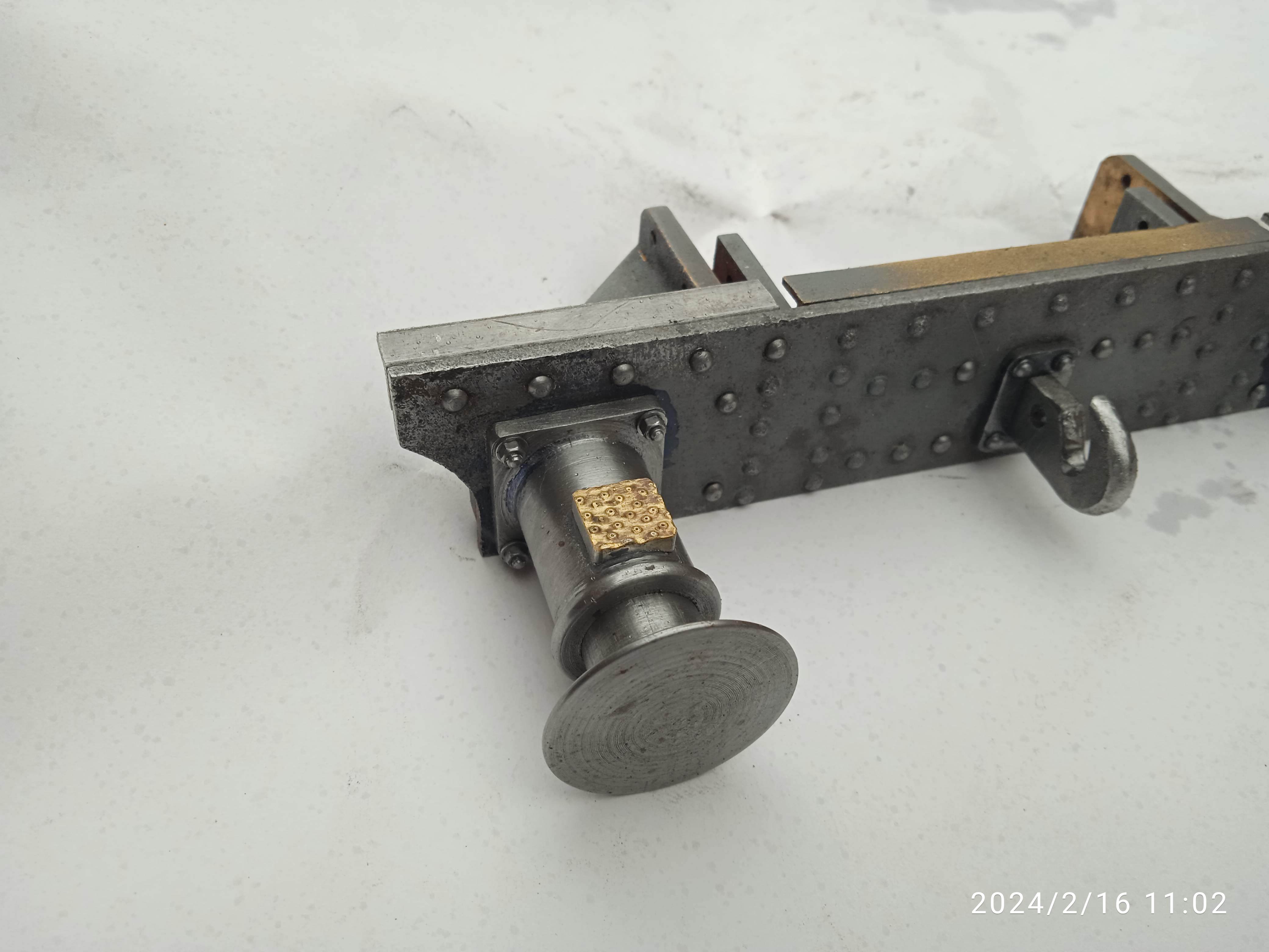
February 2024 - To get the hangers to fit, I milled 1/16th from the back of the hangers and used my Dremel to grind a 1/16th from the middle of the spring hanger support brackets. After all that, making the brake cylinders and operating arms was straight forward and all assembled O.K. With those done, attention turned to the Horn Keeps. I only had to finish making three as all the others had been made. But a problem arose trying to fit them. There was a total of four broken taps and a couple of stripped threads in the spring hanger brackets to contend with as well as some holes had been drilled to the wrong pattern. the Dremel once again came in handy with regards to grinding out the broken taps, the resulting 'mess' being drilled and tapped 1BA so a plug could be inserted then re-drilled and tapped. I ended up having to alter eight of the spring hanger brackets in one form or another. after all that, I thought some simple lathe work was in order. Turning the buffers was a pleasant diversion from manhandling the frames. for the steps on the buffers, I could have bought them but at £20 plus postage for four, I made them from scrap pieces of square bar and brass sheet. much cheaper! Likewise with the hook and coupling links. Coming in about £45 for a set, I decided to make these, the hook being a simple filing job, although I doubt the links will prove to be as easy!
Click on a photo to see the full size version